Time to read: 8 min
Can Motor Mounting Brackets Be Customized for Specific Engines?
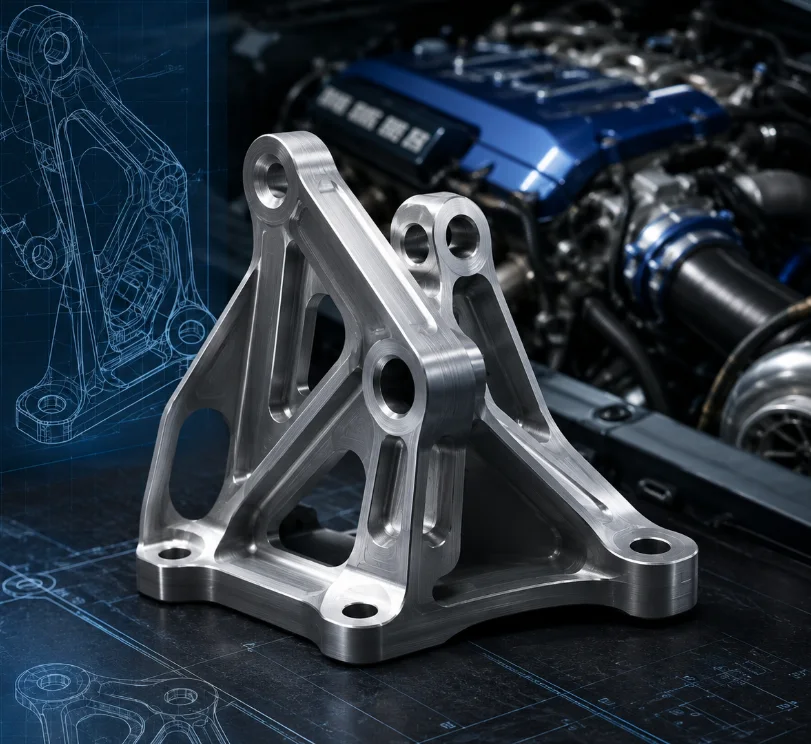
Yes. Motor mounting brackets can be customized to match a specific engine, chassis, transmission layout, isolator, and installation position. This is common in engine swaps, motorsport vehicles, restoration projects, prototypes, and industrial equipment where standard brackets cannot provide the required bolt pattern, height, offset, or clearance.
A custom bracket must do more than connect two mounting points. It must maintain powertrain alignment, transfer engine weight and torque safely, provide operating clearance, and work correctly with the selected rubber, hydraulic, polyurethane, or solid mount.
Why Do Specific Engines Need Custom Motor Mounting Brackets?
A standard bracket is designed around a particular engine, transmission, chassis, and mount system. Once one of these elements changes, the original bracket may no longer place the engine correctly.
Custom motor mounting brackets are commonly required for engine swaps, modified vehicle layouts, discontinued equipment, low-volume machines, and performance applications. They may also be needed when a standard bracket fits the engine block but creates interference with the oil pan, steering shaft, exhaust, hood, firewall, or transmission.
Custom Engine Swap Brackets
The replacement engine has its own mounting bosses, threaded holes, and block geometry, while the existing chassis has mounting points designed for another powertrain. A custom engine swap bracket connects these interfaces while controlling:
- Engine-side bolt locations
- Chassis mounting points
- Crankshaft centerline
- Transmission position
- Oil-pan and steering clearance
- Exhaust routing
- Driveline angle
- Engine movement under torque
A bracket may accept every bolt and still be incorrect if it places the engine too high, too low, too far forward, or at the wrong angle.
Modified Engine Position
An engine may be moved rearward for weight distribution, raised to clear a crossmember, lowered for hood clearance, or shifted sideways to avoid steering components.
Moving the mounting point farther from the crossmember creates a longer lever arm and increases bending at the bracket base. Practical engine-swap experience shows that a thick plate can still deflect when it forms a long unsupported arm. Longer gussets, boxed sections, triangulated supports, or a wider attachment base may be required.
Replacement and Low-Volume Applications
Older vehicles, generators, pumps, compressors, and construction equipment may use brackets that are no longer available. A replacement can be developed from an existing part, damaged sample, drawing, 3D scan, or verified engine and frame measurements.
Custom brackets are also suitable for generator sets, agricultural machines, test stands, marine systems, robotic platforms, and low-volume vehicles. In these projects, CNC machining or fabrication can avoid the tooling cost of casting or forging.
When Are Custom Motor Mounting Brackets Needed?
| Application | Why Customization Is Needed | Main Design Concern |
|---|---|---|
| Engine swap | Engine and chassis use different patterns | Position and driveline alignment |
| Motorsport vehicle | Standard mounts allow excessive movement | Strength, stiffness, and vibration |
| Restoration project | Original brackets are unavailable | Accurate reproduction |
| Modified transmission | Powertrain angle or location changes | Engine-to-transmission alignment |
| Custom chassis | No factory interface exists | Load distribution |
| Industrial equipment | Engine fits a nonstandard base | Stability and vibration |
| Steering or oil-pan modification | Engine must be moved | Dynamic clearance and leverage |
| Low-volume production | Standard parts do not fit | Repeatability and inspection |
What Can Be Customized on a Motor Mounting Bracket?
Nearly every feature can be changed, but each change should solve a defined installation problem.
Engine-Side Mounting Interface
The engine-side interface can be designed around threaded holes, bosses, dowels, and machined pads. Important details include hole spacing, thread size, thread depth, boss height, mounting-face angle, fastener clearance, and tool access.
Engines within the same family may use different block castings. The exact engine code, model year, block version, and transmission combination should be confirmed before manufacturing.
Chassis-Side Interface
The opposite side may connect to a frame rail, crossmember, subframe, cradle, pedestal, or machine base using through-bolts, threaded holes, studs, sleeves, or isolators.
A strong billet bracket cannot compensate for a weak support. If the new mounting position concentrates load into a thin crossmember or frame plate, the supporting structure may also need reinforcement.
Engine Height, Offset, and Setback
A custom bracket can control engine height, lateral offset, and fore-and-aft position. These dimensions affect hood and oil-pan clearance, steering, exhaust routing, cooling layout, transmission alignment, driveshaft angle, and service access.
Positioning the engine correctly is often harder than manufacturing the bracket. Builders commonly support the engine with a hoist or adjustable fixture, verify the powertrain relationship, and create templates only after the position is confirmed.
Mount and Isolator Interface
The bracket may connect to a rubber, hydraulic, polyurethane, or solid mount. It must match the isolator’s width, sleeve diameter, through-bolt location, compression direction, and permitted movement.
Rubber and Hydraulic Mounts
These mounts reduce vibration transmitted into the chassis. The bracket should not force them to operate at the wrong angle or under unintended preload.
The isolator and metal bracket are separate components. A worn rubber or hydraulic mount does not automatically require a new metal bracket unless the bracket is cracked, bent, corroded, or dimensionally damaged.
Polyurethane and Solid Mounts
Polyurethane and solid mounts reduce engine movement but transmit more vibration and fatigue loading. A rigid custom billet engine mount may suit a race vehicle but may be unsuitable for a road vehicle. Mount stiffness should be selected for the complete application.
What Information Is Needed to Customize a Bracket?
A reliable design review requires more than an engine name or photograph.
Engine, Transmission, and Position Data
Provide the engine manufacturer, code, model year, block type, displacement, transmission model, installed orientation, crankshaft centerline, engine height, lateral offset, setback, and powertrain angle.
The transmission must be considered with the engine because changing engine position can alter driveline and transmission-mount geometry.
3D Models and 2D Drawings
A 3D model should show the engine-side interface, chassis-side interface, isolator, and surrounding clearance envelope. A 2D drawing should define datums, critical dimensions, holes, threads, tolerances, material, finish, and inspection requirements.
When original CAD is unavailable, geometry can be developed from CMM inspection, 3D scanning, reverse engineering, or a physical sample. Scan data is useful for irregular shapes, but critical holes, threads, and machined faces should be verified with controlled measurements.
Static and Dynamic Clearance
Static clearance confirms that the engine does not interfere while stationary. Dynamic clearance accounts for engine roll, isolator deflection, braking, acceleration, chassis movement, and thermal expansion.
A custom bracket may fit in the workshop and still allow the exhaust, oil pan, or accessory drive to contact another component under load. Clearance should be checked around the steering, firewall, hood, radiator, hoses, wiring, suspension, and service tools throughout the expected movement range.
Load and Application Information
The designer should know engine mass, maximum torque, vehicle or machine type, operating temperature, shock loading, and intended service life.
Engine torque creates rotational reaction in the mounting system. One side may lift while the other is pushed downward. Braking, acceleration, road impacts, and vibration add repeated loads that can be more important than static engine weight.
What Should Be Provided to a Supplier?
| Required Information | What to Provide | Why It Matters |
|---|---|---|
| Engine identification | Code, model year, and block type | Similar engines may use different interfaces |
| Transmission information | Model and installed position | Controls angle and alignment |
| Engine-side interface | Bolt pattern, threads, and bosses | Defines the engine connection |
| Chassis-side interface | Frame or crossmember dimensions | Defines the support connection |
| Required position | Height, offset, setback, and angle | Controls fit and clearance |
| Isolator details | Mount type and dimensions | Ensures correct operation |
| Clearance envelope | Steering, exhaust, hood, and oil-pan geometry | Prevents interference |
| Load conditions | Mass, torque, use, and shock loads | Influences material and reinforcement |
| CAD and drawings | Models, datums, and tolerances | Supports production and inspection |
| Quantity | Prototype or low-volume requirement | Guides process selection |
How Are Custom Motor Mounting Brackets Designed?
The design should begin with engine position and load transfer, not appearance.
Establish Functional Datums
Datums should come from stable features such as engine mounting faces, dowel holes, machined bosses, chassis pads, or isolator bores. Irregular casting edges and flexible sheet metal should not be primary references when better features are available.
Confirm the Complete Powertrain Position
Before finalizing the bracket, confirm engine centering, crankshaft angle, transmission position, driveshaft relationship, oil-pan clearance, steering clearance, exhaust clearance, and accessory access.
This stage may require repeated mock-ups. Revising a template or CAD model is less expensive than remaking a finished bracket.
Create a Direct Load Path
Material should connect the engine interface to the chassis interface as directly as possible. Long flat plates often carry load mainly through bending. A more efficient custom motor mount bracket design may use ribs, gussets, boxed sections, triangulated supports, or a wider base.
Avoid Unsupported Lever Arms
A long offset increases bending at the base. Better solutions may include moving support closer to the load, extending ribs, adding another support, widening the attachment, or reducing the offset.
Review the Supporting Structure
The bracket may be stronger than the crossmember or engine-block boss. The bracket, fasteners, engine bosses, welds, and frame attachment should therefore be reviewed as one system.
Maintain Service Access
Reinforcement should not block oil filters, starter motors, steering joints, belts, drain plugs, control-arm bolts, or mounting fasteners. Tool access and installation sequence should be checked in CAD.
Add CNC-Machinable Geometry
CNC-machined engine mount brackets should use accessible pockets, generous internal radii, practical wall thickness, stable clamping surfaces, and open tool paths.
Internal Radii and Pockets
Round tools cannot produce perfectly sharp internal corners. Larger radii permit more rigid tools and can reduce stress concentration.
Deep, narrow pockets require long tools and increase machining time and vibration risk. Lightening pockets should follow the load path rather than a decorative pattern.
Review Fasteners and Assembly
Verify bolt diameter, grade, engagement, washer area, head clearance, socket access, insertion direction, and assembly sequence.
Slots can help prototype fitting, but they should not replace positive location where engine position must be controlled. Dowel pins, shoulders, or close-fitting features may be more suitable.
Should the Bracket Be CNC Machined or Fabricated?
Both routes can produce reliable custom motor mounting brackets.
CNC-Machined Engine Mount Brackets
CNC machining is suitable for compact brackets, adapter plates, billet aluminum parts, and components with complex three-dimensional offsets.
It can accurately control hole position, mounting-face relationships, bore size, ribs, pockets, and overall offset. It is especially useful for prototypes, motorsport vehicles, restoration parts, and repeated low-volume production.
The main limitation is material removal. A large bracket machined from solid stock can create high material and cycle costs. Billet construction is not automatically stronger than fabrication; performance still depends on material, geometry, load direction, and fatigue.
Fabricated Motor Mounting Brackets
Fabricated brackets combine plate, bent sections, tubing, gussets, sleeves, and machined bosses. This route is often economical for large steel structures and one-off engine swaps.
Welding can distort holes and mounting faces, so fixtures, controlled weld sequences, machining allowance, and post-weld inspection may be required.
Hybrid Manufacturing
A hybrid bracket uses fabricated structural elements with CNC-machined interfaces. It can reduce material waste while maintaining accurate bores, faces, and hole patterns.
CNC Machining vs Fabrication
| Factor | CNC-Machined Bracket | Fabricated Bracket |
|---|---|---|
| Best suited for | Compact, complex precision parts | Large steel structures |
| Typical materials | Aluminum, steel, and stainless steel | Steel plate, tube, and machined sleeves |
| Accuracy | High between holes and faces | Depends on fixtures and welding |
| Design flexibility | Pockets, ribs, offsets, and angled faces | Triangulated and boxed structures |
| Distortion risk | Relatively low | Welding can move features |
| Material efficiency | May remove substantial billet | Uses plate and tube efficiently |
| Repeatability | High for low-volume production | Requires controlled fixtures |
| Cost advantage | Compact, complex parts | Large or structurally simple parts |
What Materials Are Commonly Used?
6061-T6 Aluminum
6061-T6 is widely used for CNC-machined aluminum engine mount brackets because it offers good machinability, useful strength, low weight, corrosion resistance, and anodizing compatibility. It suits many prototypes and low-volume applications when the geometry provides adequate stiffness.
7075-T6 Aluminum
7075-T6 provides higher strength and may suit weight-sensitive or high-performance brackets. It is more expensive, less suitable for conventional welding, and requires attention to corrosion and fatigue-sensitive details.
Carbon Steel
Carbon steel is common for fabricated brackets because it offers high stiffness, availability, and practical weldability. Required thickness depends on grade, unsupported length, geometry, weld arrangement, engine torque, and fatigue—not a single general rule.
Stainless Steel
Stainless steel may be selected for corrosive, marine, or high-temperature environments. It is heavier and more expensive to machine than aluminum, so it is usually reserved for specialized applications.
Which Tolerances Matter Most?
Mounting Hole Position
Hole position determines whether the bracket fits without forcing bolts sideways. The pattern should be controlled from functional datums.
Mounting-Face Flatness
Flat faces reduce rocking, uneven bolt loading, and distortion. Fabricated brackets may need post-weld machining.
Bore and Sleeve Fit
Bushing bores and sleeves must provide the intended fit. Oversized bores allow movement, while undersized bores prevent assembly.
Bracket Offset
The distance between engine-side and chassis-side interfaces controls engine position. A small error can affect driveline angle, hood clearance, and oil-pan clearance.
Nonfunctional profiles and cosmetic pockets can normally use wider tolerances to control cost.
How Should a Custom Bracket Be Prototyped and Inspected?
Physical Mock-Up and Assembly
Support the engine in the required position and use templates or 3D-printed patterns to verify shape, bolt access, and clearance. Install the prototype with the intended mounts and fasteners. Confirm that the faces seat fully, all bolts remain accessible, the transmission aligns, and no forced assembly is required.
Dynamic and Structural Validation
Move the engine through the expected isolator travel and check the steering, exhaust, oil pan, firewall, hoses, wiring, and accessories.
Depending on the application, validation may include hand calculations, finite element analysis, fastener calculations, fatigue review, weld assessment, or physical testing.
Inspection
Typical inspection items include hole position, bore diameter, thread quality, mounting-face flatness, interface spacing, bracket offset, weld quality, and surface-treatment coverage. CMM inspection or a dedicated fixture may be useful for repeated production.
What Surface Treatments Are Suitable?
Aluminum brackets may be anodized or hard anodized. Carbon-steel brackets may use zinc plating, black oxide, paint, or powder coating.
Precision bores, threads, mounting faces, and grounding areas may require masking because coating thickness can change fit and contact conditions.
How Does RapidMFGPro Support Custom Motor Mounting Bracket Projects?
RapidMFGPro helps buyers connect custom bracket requirements with suitable manufacturing suppliers. It operates as a supplier-matching and project-communication platform rather than presenting every part as production from one in-house factory.
Matching the Manufacturing Route
A billet aluminum bracket may require multi-axis CNC milling, while a large steel bracket may need cutting, bending, welding, and finish machining.
RapidMFGPro helps align the project with suppliers suited to the required process, material, quantity, geometry, and inspection level. This is useful when buyers are uncertain whether a bracket should be machined, fabricated, or produced through a hybrid route.
Supporting DFM Communication
Custom brackets often contain deep pockets, sharp internal corners, inaccessible bolts, long unsupported arms, or unnecessarily tight tolerances.
RapidMFGPro can support communication between buyers and potential suppliers around manufacturability. Possible revisions may include larger internal radii, reduced pocket depth, improved tool access, stronger ribs, clearer datums, or more practical tolerances.
Prototype and Low-Volume Sourcing
Many projects begin with one prototype or a small validation batch. RapidMFGPro supports prototype and low-volume sourcing by helping keep drawings, material requirements, design revisions, surface treatment, and inspection expectations connected through the quotation and production process.
RFQ Preparation
For a useful supplier match, buyers should submit 2D drawings, 3D models, engine and chassis interface information, material, quantity, isolator details, critical tolerances, surface treatment, application notes, and inspection requirements.
A complete RFQ reduces repeated clarification and helps potential suppliers evaluate machining setups, welding needs, post-processing, and inspection before quoting.
Conclusion
Motor mounting brackets can be customized for a specific engine, but the design must consider engine position, driveline alignment, isolator movement, dynamic clearance, material, and load transfer.
CNC machining suits compact, accurate, low-volume brackets, while fabrication is often better for larger steel structures. RapidMFGPro helps connect these requirements with suitable suppliers and supports clearer communication from RFQ review through prototype and low-volume production.
Need Help Reviewing a Custom Part?
Share your CAD file and requirements to request supplier matching. Supplier capability and commercial terms must be verified before order placement.
Request Supplier Match