Time to read: 8 min
Press Fit & Interference Fit Calculator
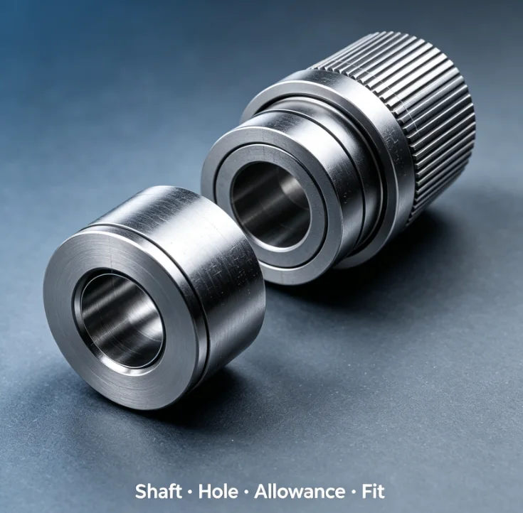
Use this press fit calculator to estimate diametral interference, interface pressure, press-in force, axial holding force, and torque capacity for a cylindrical shaft-and-hub joint. You can calculate one measured size pair or compare minimum, nominal, and maximum conditions from manufacturing tolerance limits.
Press Fit & Interference Fit Calculator
Compare interference, contact pressure, press-in force, holding force and torque under actual or tolerance-limit dimensions.
Geometry & Fit
Dimensions before assemblyMaterial Properties
Preliminary elastic-cylinder estimate. Validate critical joints with material data, surface condition and assembly trials.
Assumes concentric cylindrical parts, uniform contact, isotropic elastic behavior and constant friction. Edge effects, roughness, coatings and plasticity are excluded.
Use the result as an early design check—not as final validation for safety-critical joints.
Review My Press-Fit PartHow to Use This Press Fit Interference Calculator
Choose Actual Dimensions or a Tolerance Range
Use Actual dimensions when you know the measured bore and shaft diameters. Select Tolerance range when reviewing a drawing or planning press fit tolerancing. In tolerance mode, the calculator checks the loosest assembly, the nominal condition, and the tightest assembly rather than reporting only one ideal value.
Enter the Joint Geometry
Enter the hub bore, shaft diameter, hub outside diameter, engagement length, and—if applicable—the inside diameter of a hollow shaft. The hub outside diameter affects its radial compliance, while engagement length directly affects the estimated press-in and holding forces.
Select Materials and Friction
Select the shaft and hub materials to load representative elastic properties. The friction coefficient strongly influences assembly force, holding force, and torque capacity. Replace the default value with data that reflects lubrication, surface finish, coating, and the actual material pair whenever reliable test data is available.
How to Read the Press Fit Calculator Results
Diametral Interference and Interface Pressure
Diametral interference is the shaft diameter minus the bore diameter before assembly. A positive value indicates a press-fit condition. The estimated interface pressure is the radial contact pressure created as the hub expands and the shaft contracts elastically.
Estimated Press-In Force
The displayed press-in force is a theoretical sliding-force estimate based on interface pressure, cylindrical contact area, and the selected friction coefficient. Real press in force measurement may be higher or lower because of lead-in chamfers, alignment, lubrication, surface roughness, speed, temperature, and local plastic deformation.
Holding Force and Torque Capacity
Axial holding force estimates the load required to make the fitted surfaces slip axially. Torque capacity estimates the torsional load that friction can transmit. Both values are preliminary; shock loading, cyclic operation, contamination, and temperature changes require additional engineering checks.
Why Tolerance Limits Matter for Press Fits
A useful press fit tolerance calculator must consider worst-case manufactured sizes. The minimum-interference condition combines the smallest shaft with the largest bore. The maximum-interference condition combines the largest shaft with the smallest bore.
Minimum interference: checks whether the joint could become too loose, slip, or lose torque capacity.
Nominal interference: estimates the expected assembly condition near the centers of both tolerance zones.
Maximum interference: checks the highest contact pressure, press force, hub stress, and assembly difficulty.
For a tolerance for bearing press fit, do not select the fit from a general press fit interference chart alone. Bearing type, rotating load, ring material, housing stiffness, operating temperature, and the bearing manufacturer’s recommendations can change the required tolerance.
Calculation Method and Engineering Assumptions
How Contact Pressure Is Estimated
To answer how to calculate contact force, the tool first estimates interface pressure with an elastic thick-cylinder model. It accounts for shaft stiffness, hub stiffness, Poisson’s ratio, hub wall thickness, and a hollow-shaft bore where entered. Contact force is then related to pressure multiplied by the cylindrical contact area.
How Press-In Force Is Estimated
The simplified relationship is F = μ × p × π × d × L, where μ is the friction coefficient, p is interface pressure, d is the contact diameter, and L is engagement length. This is a theoretical estimate for aligned cylindrical parts; it is not a substitute for measured force-displacement data from the actual assembly process.
Model Limits
The calculation assumes concentric geometry, uniform contact, isotropic materials, elastic behavior, and constant friction. It excludes edge effects, form error, coating buildup, roughness deformation, thermal gradients, yielding, and residual stress. Validate critical or safety-related press fits with current material data, applicable standards, simulation, and physical assembly trials.
Worked Example: Steel Shaft in a Steel Hub
Example input: 25.000 mm hub bore, 25.035 mm shaft, 50 mm hub OD, 30 mm engagement length, solid shaft, steel shaft and hub, and a friction coefficient of 0.15.
Interpretation: The 35 µm diametral interference creates positive interface pressure. The calculator then estimates assembly force, axial retention, torque transmission, and hub bore hoop stress. Before releasing the drawing, the engineer should also verify material strength, entrance chamfers, surface finish, lubrication, temperature, and how both diameters will be inspected.
CNC Machining and Inspection Recommendations
Control the Functional Diameters
Specify bore and shaft limits directly on the drawing and identify whether dimensions apply before or after heat treatment, anodizing, plating, or coating. For tight press fits, roundness, cylindricity, taper, and surface finish can be as important as the two-point diameter measurement.
Provide an Assembly Lead-In
Add a suitable chamfer or radius to help center the shaft and reduce edge damage during assembly. Avoid sharp entries that can scrape material, create burrs, or cause an artificially high press force.
Plan Verification Around the Tolerance Range
Inspect the bore and shaft with equipment appropriate to the tolerance and geometry. Record actual sizes during first-article inspection, and compare real press-force curves with the calculated range when the joint function depends on retention or torque.
Frequently Asked Questions
What is press fit interference?
Press fit interference is the positive dimensional difference between the shaft outside diameter and the mating bore diameter before assembly. The parts deform during assembly and create contact pressure.
Is a pressure fit the same as a press fit?
Pressure fit is sometimes used informally for a press fit or interference fit. On an engineering drawing, use recognized fit terminology and explicit dimensional tolerances to avoid ambiguity.
How much interference should a bearing press fit use?
There is no universal value. The correct tolerance for a press fit bearing depends on bearing size, load direction, ring rotation, housing or shaft material, wall thickness, temperature, and the bearing manufacturer’s fit tables.
Why does measured press-in force differ from the calculator?
Measured force is affected by friction variation, lubricant, chamfers, misalignment, surface texture, coatings, insertion speed, temperature, debris, and local yielding. Treat the calculated value as a screening estimate.
Can this tool replace an ISO fit table?
No. This tool evaluates entered dimensions or tolerance limits. Use the applicable ISO system, bearing guidance, or company standard to select the fit, then use the calculator to compare the resulting assembly conditions.
Need a Supplier for Your Press-Fit Parts?
Submit your shaft, hub, or bearing-seat drawings. RapidMFGPro can help review the tolerance strategy, material pairing, inspection requirements, and suitable manufacturing route before matching the project with potential suppliers.
Need Help Reviewing a Custom Part?
Share your CAD file and requirements to request supplier matching. Supplier capability and commercial terms must be verified before order placement.
Request Supplier Match