Time to read: 8 min
Turning Titanium: A Practical Guide to Inserts, Speeds, Feeds, Tool Wear, and Surface Finish
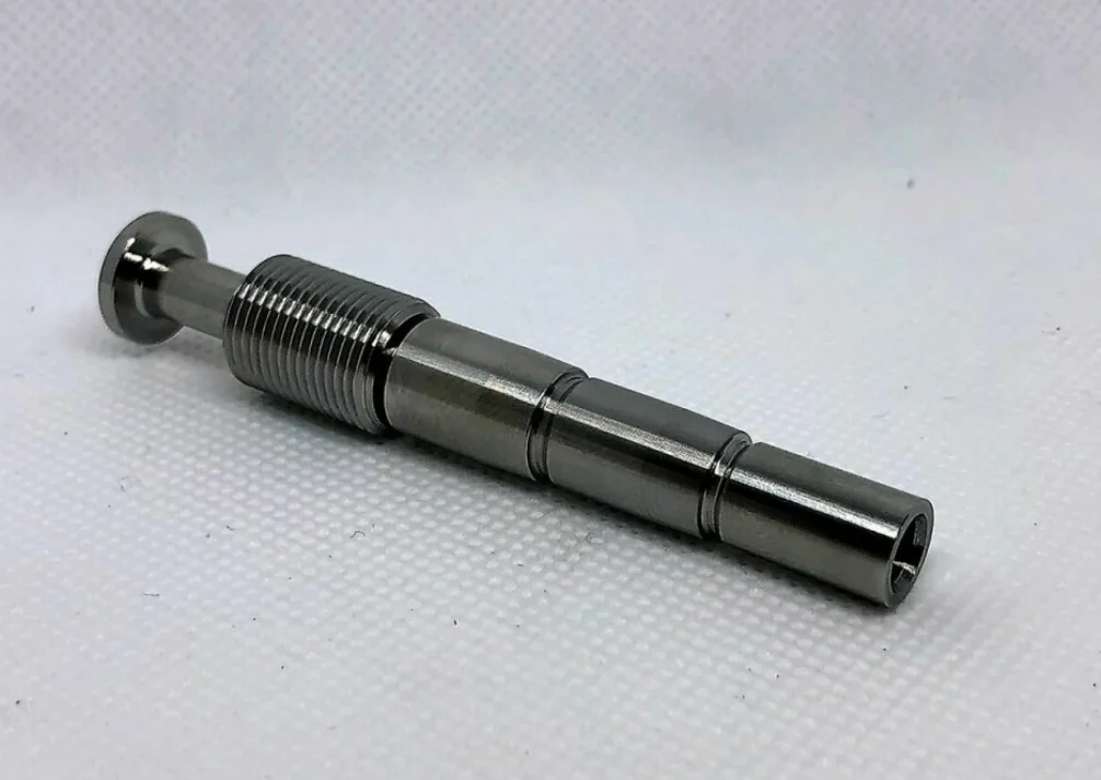
Turning titanium is not difficult simply because the material is strong. The real challenge is that titanium retains heat near the cutting edge, tends to adhere to tools, produces difficult chips, and can create high cutting forces when the tool, parameters, or setup are not properly matched. A setting that works for a rigid external turning operation may fail during boring, grooving, threading, or machining a thin-wall component.
This guide explains how titanium grade, insert geometry, cutting speed, feed, depth of cut, coolant delivery, machine rigidity, and part design interact. It also shows how to diagnose rapid insert failure, chatter, poor surface appearance, chip recutting, and dimensional drift. The purpose is not to provide one universal RPM. It is to help machinists, engineers, and buyers identify the conditions that determine a reliable titanium turning process.
Why Is Titanium Difficult to Turn?
Heat Remains Concentrated Near the Cutting Edge
Titanium has relatively low thermal conductivity compared with many commonly machined steels and aluminum alloys. During turning, a large share of the generated heat remains in the cutting zone instead of being carried rapidly into the workpiece. The insert therefore experiences a high localized thermal load, especially when cutting speed is excessive or coolant cannot reach the tool-chip interface.
This does not mean that the workpiece always feels exceptionally hot. The insert can be exposed to damaging temperatures while the bulk of the component remains much cooler. Crater wear, loss of edge strength, adhesion, and sudden chipping may consequently appear earlier than a machinist expects.
Titanium Can Adhere to the Cutting Edge
Titanium has a strong chemical affinity with many cutting-tool materials at elevated temperature. Workpiece material can weld to the insert, form a built-up edge, and then tear away. When the adhered material detaches, it may remove part of the cutting edge or leave an irregular surface on the component.
A dull insert, unsuitable edge preparation, inadequate lubrication, or parameters that cause rubbing rather than cutting can intensify this behavior. The resulting surface may look smeared or torn even when the nominal tool path appears correct.
Elastic Recovery Raises the Risk of Rubbing
Titanium has a lower modulus of elasticity than steel. The material can deflect under the cutting force and recover after the tool passes. This springback is especially important in thin walls, slender shafts, small bores, and other low-rigidity features. If the feed or finishing allowance is too small, the cutting edge may slide over the recovering surface instead of producing a stable chip.
Repeated light passes are therefore not always gentle on the insert. They may increase heat, promote adhesion, and leave an affected surface that is more difficult for the next pass to cut.
Long Chips Can Damage the Tool and Finished Surface
Titanium often produces long, tough, continuous chips. If the chipbreaker is not operating within its intended feed and depth-of-cut range, the chip may wrap around the component, collect in a bore, strike the insert, or pass through the cutting zone again. Chip recutting can chip the edge and scratch a surface that was otherwise machined correctly.
These characteristics are connected. Heat promotes adhesion, adhesion changes the effective cutting geometry, unstable chip formation increases the load on the edge, and a flexible setup magnifies the disturbance. Successful titanium turning therefore depends on the complete cutting system rather than on RPM alone.
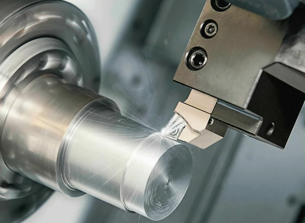
How Do Grade 2 and Grade 5 Titanium Differ in Turning?
Commercially Pure Grade 2 Titanium
Grade 2 is commercially pure titanium. It has lower strength than Ti-6Al-4V, but this does not automatically make it effortless to machine. Grade 2 can be gummy, prone to adhesion, and capable of producing long stringy chips. A sharp, positive cutting geometry and effective chip control are particularly important.
During finishing, an edge that is too heavily honed may push or smear the material. During roughing, an unsuitable chipbreaker may fail to curl and break the chip even when spindle load appears acceptable.
Ti-6Al-4V Grade 5 Titanium
Grade 5, commonly identified as Ti-6Al-4V, is a high-strength alpha-beta titanium alloy used widely in aerospace, medical, energy, automotive, and industrial applications. It normally generates higher cutting forces than Grade 2 and has a narrower practical process window. Tool wear and thermal damage can accelerate quickly if speed is too high or the edge loses sharpness.
Grade 5 also exists in different material conditions and product forms. Bar stock, forged stock, cast material, and additively manufactured material may not behave identically. Surface condition, residual stress, hardness variation, and interrupted material at the outside diameter or inside a printed bore can change the load on the insert.
Why the Grade Must Be Confirmed Before Selecting Parameters
A drawing that states only “titanium” does not provide enough information for a responsible quotation or process plan. At minimum, the grade, specification, material condition, stock form, certification needs, and any traceability requirements should be defined.
| Factor | Grade 2 | Grade 5 (Ti-6Al-4V) | Turning implication |
|---|---|---|---|
| Material type | Commercially pure titanium | Alpha-beta titanium alloy | Do not apply one parameter set to both materials |
| Typical strength | Lower | Higher | Grade 5 generally creates greater cutting load |
| Common cutting concern | Adhesion, smearing, and stringy chips | Heat, edge wear, and high cutting forces | Geometry and chip control must reflect the grade |
| Material condition | Specification dependent | Annealed or other specified conditions | Confirm condition before quoting or programming |
Other grades, including Grade 23 Ti-6Al-4V ELI, beta titanium alloys, and specialty high-temperature grades, require their own review. Even when two grades have similar names, their mechanical properties, certification requirements, and machining response may differ.
How Should You Choose an Insert for Turning Titanium?
Start with a Titanium-Compatible Carbide Grade
For repeatable CNC production, a fine-grain carbide insert designed for heat-resistant alloys is a common starting point. The appropriate grade and coating depend on the insert manufacturer, cutting mode, coolant strategy, and required balance between sharpness and edge strength. Uncoated or thin-coated grades may be suitable in some conditions because they preserve a sharp edge, while modern titanium-compatible coatings can improve thermal and wear resistance in other applications.
The coating name by itself is not enough. A coating that performs well on one substrate and edge preparation can fail on a different insert. Use the tool manufacturer's material group, application chart, and operation-specific data rather than selecting an insert only because its catalog description mentions titanium.
Use Positive Geometry to Reduce Cutting Pressure
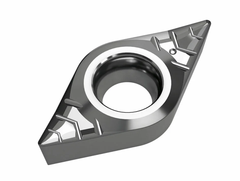
Positive rake geometry generally reduces cutting forces and helps the insert shear titanium instead of pushing it. This is useful for thin walls, slender components, boring bars, and finishing operations. A sharp edge can also limit adhesion and reduce the tendency to smear Grade 2 titanium.
However, the sharpest possible edge is not always the strongest. Interrupted cuts, scale, forged surfaces, additive-manufactured skin, or an unstable setup may require more edge support. Insert selection must balance sharpness against the mechanical load and the risk of chipping.
Match Edge Preparation to the Actual Operation
A heavily honed edge can withstand load but may generate excessive pressure in a flexible finishing setup. A very sharp edge can cut cleanly but may be vulnerable during interruption or heavy roughing. The appropriate edge preparation changes with external turning, boring, grooving, threading, stock condition, and setup rigidity.
For example, an insert that performs acceptably during rigid OD roughing may fail in a small bore because the boring bar deflects and chips cannot escape. Changing only the carbide grade would not correct the underlying difference.
Select a Chipbreaker for the Planned Feed and Depth of Cut
A chipbreaker does not break chips automatically. The chip must have sufficient thickness and follow the designed path across the insert. If feed or depth of cut falls outside the chipbreaker's working range, the chip may remain straight and continuous.
Review the manufacturer's chipbreaker diagram for the specific insert size. A roughing chipbreaker, medium-machining chipbreaker, and finishing chipbreaker are designed for different engagements. This is one reason that a single insert and a single parameter set should not be expected to handle roughing, finishing, boring, and profiling equally well.
Choose Nose Radius with Rigidity in Mind
A larger nose radius can support the edge and improve theoretical surface finish at a given feed, but it also increases radial cutting force. On a thin wall, slender shaft, or extended boring bar, the extra force can cause chatter, taper, or dimensional springback. A smaller radius reduces radial load but may require a lower feed to achieve the desired roughness.
The nose radius, feed, finishing allowance, and setup rigidity must be selected together. Changing the radius without adjusting the feed can alter both surface finish and chip formation.
How Should You Set Speed, Feed, and Depth of Cut?
Use Cutting Speed Instead of a Universal RPM
RPM is determined by cutting speed and the diameter being machined. The same RPM produces very different surface speeds on a 10 mm shaft and a 100 mm shaft. Recommended starting data should therefore be expressed as surface feet per minute (SFM) or meters per minute (m/min), then converted for the current diameter.
Metric formula: RPM = (cutting speed in m/min × 1,000) ÷ (π × diameter in mm)
Inch formula: RPM = (SFM × 12) ÷ (π × diameter in inches)
On a CNC lathe, constant surface speed can maintain a more consistent cutting condition as the tool moves across a changing diameter. A maximum spindle-speed limit remains essential, particularly near the center of a face or on a workpiece with limited balance or clamping security.
Establish Feed from Chip Formation and Surface Requirements
Feed must be high enough for the edge to cut and for the chipbreaker to function, but not so high that cutting load exceeds the rigidity of the tool, component, or fixture. The appropriate feed also depends on nose radius and the required surface finish.
Extremely low feed can cause rubbing, heat, adhesion, and premature edge damage. Excessive feed can overload the insert, create chatter, or make it impossible to achieve the specified finish. Review the insert manufacturer's feed range, then validate it with chip shape, spindle load, tool wear, surface condition, and dimensional stability.
Use a Depth of Cut That Produces Stable Engagement
Repeated shallow passes are often used in an attempt to protect the tool, but titanium generally benefits from a decisive and stable cut. During roughing, the depth should place the cutting edge beneath an affected or irregular surface while remaining within the insert's capacity and the rigidity of the setup.
If every pass ends at the same depth-of-cut line, localized notch wear may develop. A process engineer may vary the depth, distribute stock between tools, or change the roughing strategy when notch wear becomes the limiting failure mode.
Separate Roughing and Finishing Strategies
Roughing prioritizes material removal, reliable chip control, predictable tool life, and stable cutting forces. Finishing prioritizes size, geometry, surface roughness, and appearance. These operations may require different inserts, nose radii, chipbreakers, speeds, feeds, and coolant strategies.
Leave enough finishing stock to produce a continuous chip. If the allowance is inconsistent or too small, the finishing insert may alternate between cutting and rubbing. If it is excessive, a nominal finishing pass becomes an uncontrolled semi-roughing pass and may deflect a thin feature.
| Operation | Cutting-speed direction | Feed priority | DOC priority | Main warning |
|---|---|---|---|---|
| External roughing | Begin conservatively | Maintain positive chip formation | Keep the edge below an affected surface | Avoid repeated light passes |
| External finishing | Adjust for finish and tool condition | Match feed to nose radius | Leave consistent finishing stock | Do not finish with a worn edge |
| Boring | Often more conservative than OD turning | Avoid rubbing while controlling bar load | Balance engagement with bar rigidity | Watch chip packing and overhang |
| Grooving and parting | Conservative because heat is concentrated | Maintain stable feed | Keep the blade engaged | Do not dwell in the groove |
| Threading | Follow the insert-system recommendation | Use a controlled infeed strategy | Distribute load over planned passes | Avoid rubbing during final passes |
This table gives a decision direction, not substitute cutting data. Final starting values should come from the tool manufacturer's current recommendations for the exact insert, titanium grade, operation, coolant condition, and machine capability.
Why Do Titanium Turning Inserts Wear or Chip So Quickly?
Identify the Failure Mode Before Changing Parameters
Calling every damaged insert “worn out” hides the cause. Gradual flank wear, crater wear, depth-of-cut notching, built-up edge, edge chipping, and sudden fracture point to different process problems. Inspect the insert under magnification and record where the damage begins.
Gradual, repeatable wear may be managed by optimizing cutting speed and coolant or by scheduling a tool change. Random fracture is more likely to indicate chatter, interrupted load, chip impact, poor seating, excessive overhang, or another mechanical problem.
Why an Insert May Shatter During Boring
Boring combines reduced tool rigidity with restricted coolant access and difficult chip evacuation. A long or undersized boring bar can deflect and vibrate. Chips can pack ahead of the insert, strike the cutting edge, or be recut. Coolant may enter the bore without reaching the tool-chip interface.
When an insert breaks partway through a bore, check bar overhang, bar diameter, holder condition, cutting-edge height, insert seating, chip evacuation, and coolant direction before merely lowering RPM. A stiffer bar, shorter overhang, through-tool coolant, appropriate chipbreaker, or revised tool path may be more effective than a speed change.
Why Lower Speed Does Not Always Stop Chipping
Reducing speed may help when thermal wear is the cause. It will not remove chatter caused by a flexible setup, prevent chips from striking the insert, correct an off-center tool, or strengthen an inadequately clamped component. Excessively low effective speed may also worsen built-up edge in some conditions.
Change one controlled factor at a time and document the result. If speed, feed, depth, insert, coolant, and tool path are all changed together, it becomes difficult to identify which factor improved or damaged the process.
When Should an Insert Be Replaced?
In repeat production, the insert should normally be indexed or replaced before catastrophic failure. A broken insert can damage the component, holder, bore, or machine and may leave fragments that affect the next cut.
Useful indicators include dimensional trend, surface change, chip color and form, spindle load, sound, machining time, and the number of completed components. Establish a conservative tool-life limit during process validation, then refine it using recorded evidence. Tool changes based on a stable wear limit are more economical than waiting for every edge to fracture.
| Insert condition | Likely causes | Check first | Possible correction |
|---|---|---|---|
| Gradual flank wear | Excessive speed, heat, or insufficient cooling | Wear trend and coolant direction | Moderately reduce speed and improve coolant delivery |
| Sudden edge chipping | Chatter, interruption, or chip impact | Setup rigidity and chip evacuation | Shorten overhang and prevent chip recutting |
| Notch at the DOC line | Surface condition or repeated depth of cut | Exact wear location | Vary DOC or revise the roughing strategy |
| Material welded to the edge | Adhesion, rubbing, or a dull edge | Edge sharpness and actual engagement | Use suitable sharp geometry and improve lubrication |
| Insert fracture in a bore | Bar deflection, chatter, or packed chips | Bar overhang and bore evacuation | Use a stiffer bar and directed coolant |
How Can You Prevent Rubbing and Work Hardening?
Keep the Tool Cutting Instead of Sliding
The cutting edge needs sufficient engagement to form a chip. When the undeformed chip thickness is too small relative to the edge radius, the tool can plough or rub instead of shearing the material cleanly. This creates heat without useful material removal and can promote adhesion.
Use a sharp edge suitable for the operation, maintain a feed that works with the nose radius and chipbreaker, and confirm that the component is not deflecting away from the tool. A programmed feed does not guarantee the same effective chip thickness if a thin wall or boring bar is moving under load.
Avoid Repeated Light Passes
Multiple shallow “clean-up” passes can expose the insert repeatedly to the same affected surface. The edge may rub, generate heat, and leave the next pass more difficult. This is especially problematic when the tool is dull or the component springs away.
Plan stock removal so each roughing pass has stable engagement and the finishing pass receives a consistent allowance. If a spring pass does not change the measured size, repeating it may only damage the surface and insert. Investigate deflection, tool wear, temperature, and measurement method instead.
Do Not Dwell at the End of a Cut
Dwelling at a shoulder, groove bottom, thread termination, or blind-bore end allows the edge to rub in one location while heat continues to build. Program a controlled exit, relief feature, or retraction that suits the geometry. Confirm that deceleration at the end of a CNC path does not unintentionally create a dwell-like condition.
Leave a Predictable Finishing Allowance
Finishing stock must be sufficient for the insert to cut continuously but low enough to control force and deflection. The correct allowance depends on component size, wall thickness, material condition, roughing stability, heat treatment, tool radius, and the required tolerance.
Instead of defining one allowance for all titanium parts, verify that the roughing process produces consistent stock around the entire surface. Variation in allowance can cause the finishing tool to alternate between cutting heavily and rubbing.
How Should You Control Heat, Coolant, and Chips?
Put Coolant Where Heat Is Generated
Coolant being switched on does not mean that it reaches the cutting edge. A broad stream may be deflected by the rotating component or chip. During boring, coolant may fill the bore while the tool-chip interface remains poorly supplied.
Directed coolant should reach the rake face and cutting zone consistently. Through-tool or high-pressure delivery can improve heat control, lubrication, chip curling, and chip evacuation when the machine, holder, and insert system support it. The required pressure and flow depend on the operation and tool system; pressure alone cannot compensate for a nozzle aimed at the wrong location.
Keep Coolant Delivery Consistent
Intermittent coolant can subject the insert to repeated heating and cooling. In a continuous titanium turning process designed for wet machining, a stable supply is normally preferable to an irregular stream. Deep bores, grooves, and parting cuts need particular attention because the tool can move beyond the effective coolant zone.
Monitor filtration and concentration as well as direction. Contaminated or poorly maintained coolant can affect lubrication, surface quality, corrosion behavior, and process consistency.
Match the Chipbreaker to Feed and Depth of Cut
If titanium produces a continuous ribbon, first check whether the current feed and depth place the chipbreaker within its designed operating window. Increasing feed can sometimes improve chip breaking, but it also raises cutting force and may not be suitable for a thin wall or flexible bar. A different chipbreaker may be required.
Observe whether chips break reliably throughout the operation, not only during the first pass. Changing diameter, allowance, material condition, or tool wear can alter chip behavior.
Prevent Chips from Returning to the Cutting Zone
Long chips can wrap around a shaft, pack in a bore, become trapped in a groove, or scratch a finished diameter. Automated production requires a process that breaks and clears chips consistently without an operator pulling them away.
Possible corrections include a compatible chipbreaker, adjusted feed and depth, directed coolant, a revised tool path, programmed chip-breaking cycles where appropriate, and improved clearance around the operation. Never reach into a running machine or attempt to remove titanium chips by hand; they can be sharp, hot, and difficult to control.
How Can You Reduce Chatter and Improve Surface Finish?
Correct Rigidity Before Chasing Speeds and Feeds
Before making repeated parameter changes, inspect the mechanical setup in a fixed order:
- Reduce workpiece overhang where possible.
- Shorten boring-bar or toolholder overhang.
- Use the largest practical bar or holder section.
- Confirm cutting-edge center height.
- Inspect insert seating and holder condition.
- Verify chuck contact, clamping force, soft-jaw fit, and tailstock support.
A flexible setup can respond unpredictably to lower speed. It may simply chatter at a different frequency. Removing the mechanical source provides a wider and more stable parameter window.
Match Nose Radius to Setup Rigidity
A large nose radius can create an attractive theoretical finish, but it also produces greater radial force. If chatter begins after changing to a larger radius, the setup may not be rigid enough for the new load. A smaller radius with a feed selected for the required roughness can perform better.
For a thin wall or small boring bar, prioritize stability over a catalog surface-finish calculation. The calculated roughness assumes an ideal rigid system and does not include vibration, adhesion, chip scratches, or material springback.
Diagnose the Surface Pattern Before Adjusting the Process
Periodic waves or evenly spaced bands often indicate vibration. Regular feed marks may reflect the programmed feed and nose radius. Random scratches can come from uncontrolled chips. Torn or smeared areas can indicate built-up edge, a dull insert, or insufficient effective chip thickness. An orange-peel appearance may relate to material microstructure, surface condition, residual stress, or an unstable cutting action.
Photograph the surface under consistent lighting, inspect the edge, record the tool position and direction, and compare the defect spacing with feed and spindle rotation. This evidence is more useful than describing every poor finish simply as chatter.
Why a Low Ra Value Can Still Look Poor
Surface roughness and visual appearance describe related but different characteristics. A stylus measurement samples a defined path with specified cutoff settings. The appearance seen by the eye also depends on lay direction, reflection, waviness, tool-mark regularity, color, and localized material dragging.
A component can therefore meet an Ra requirement and still look visually inconsistent. If appearance is functional or commercially important, the drawing or purchase specification should define an approved visual standard, lay requirement, post-processing condition, or representative sample instead of relying on Ra alone.
How Should You Bore, Groove, Part, and Thread Titanium?
Boring Titanium
Use the shortest and largest-diameter boring bar that the feature permits. Keep the insert on center, ensure secure seating, and limit overhang according to the bar manufacturer's recommendations. Carbide or damped bars may expand the usable range for demanding bores, but they do not eliminate the need for correct engagement and chip evacuation.
Directed internal coolant is valuable because it can reach the cutting edge and push chips out of the bore. Select a chipbreaker that functions at the planned feed and depth. If chips pack in a blind bore, change the evacuation strategy before edge damage becomes catastrophic. Monitor bore taper and size drift, which can reveal bar deflection or progressive wear before the insert fractures.
Additively manufactured titanium bores deserve separate review. Surface skin, interrupted material, porosity, support remnants, and inconsistent stock can produce cyclic load. A stable pilot feature or preliminary operation may be necessary before precision boring.
Grooving and Parting Titanium
Grooving and parting concentrate heat along a narrow edge while surrounding material restricts coolant and chip movement. Use the narrowest blade that remains sufficiently rigid for the depth and diameter. Minimize blade overhang and verify that the holder is square to the workpiece.
Maintain a stable feed rather than dwelling or repeatedly rubbing the groove walls. Deliver coolant directly into the cut using a tool system intended for the operation. Chip shape must allow evacuation without jamming between the blade and groove. As the part approaches separation, the program may require a controlled change in conditions, but it should not allow the tool to rub at the center.
Threading Titanium
Threading makes repeated passes along the same profile, so the infeed method has a significant effect on edge load and rubbing. Radial, flank, or modified-flank infeed should be selected according to the insert system, pitch, thread form, machine control, and material behavior. Distribute material removal across the planned passes instead of leaving numerous extremely light final passes.
Provide an adequate runout or relief groove where the design permits. Internal threads require particularly reliable chip evacuation. Control burrs at the thread start and exit, and verify the completed feature using the specified gauges or measurement method. For safety-critical or high-value components, include thread inspection and tool-life control in the process plan rather than inspecting only the first piece.
How Can You Turn Thin-Wall and Slender Titanium Parts Without Distortion?
Reduce Clamping Distortion in Thin Walls
A thin titanium sleeve can measure correctly while held in the chuck and become out of round after release. Excessive jaw pressure, limited contact area, and poorly fitted hard jaws can distort the component during machining. Use bored soft jaws, increased contact area, controlled clamping pressure, or a mandrel where appropriate.
Validate the process by measuring the part after unclamping and after it returns to a stable temperature. An in-machine measurement alone cannot reveal every clamping-related error.
Plan the ID and OD Sequence
The order of internal and external turning determines how much material remains to support the part. In some components, boring the ID while a stronger OD remains provides useful rigidity. In others, a temporary internal support or mandrel makes it possible to finish the OD without collapse.
Rough both surfaces in a sequence that balances stress release and preserves stiffness. Leave controlled finishing stock, then complete critical features using datums and clamping conditions that support the required concentricity, wall thickness, and runout.
Support Slender Shafts
Long shafts can bend away from the tool and vibrate. Reduce unsupported length using a tailstock, steady rest, follower rest, subspindle, or appropriate guide where the design and machine permit. Segmenting the cut can help, but the transitions between sections must not create diameter steps or inconsistent finish.
Select geometry and nose radius that limit radial force. Tool sharpness is especially important because a dull edge pushes the shaft before it cuts. The manufacturing plan should consider length-to-diameter ratio during quotation; a slender shaft may require substantially more support, inspection, and cycle time than a short part with the same nominal diameter.
Control Temperature and Springback Before Final Inspection
A titanium part measured immediately after cutting may not remain at the same dimension after cooling. Elastic recovery and residual-stress redistribution can also change size or geometry after material removal and unclamping.
For tight-tolerance parts, define a consistent inspection temperature, allow stabilization when necessary, and verify the component in its free state. Large stock removal may require staged roughing, intermediate stabilization, or a revised sequence. These decisions depend on geometry, stock condition, tolerance, and production quantity.
Can You Turn Titanium on a Manual or Small Lathe?
Machine Condition Matters More Than the Label
Titanium can be turned on some manual and small lathes, but “small lathe” does not describe rigidity, spindle condition, toolholding, or the difficulty of the component. A short Grade 2 bar with a simple diameter is different from a deep Grade 5 bore or a slender shaft.
Check spindle and slide rigidity, backlash, tool-post security, available speed range, workholding, the ability to maintain a steady feed, coolant delivery, and chip control. Keep the workpiece and tool overhang short. Begin from reputable tool data and adjust cautiously based on the actual cut.
HSS or Carbide?
A properly ground, very sharp high-speed-steel tool can machine titanium in low-speed, one-off manual work, particularly when the operator can maintain the edge and control the cut. Carbide is normally more suitable for repeatable production, higher cutting speeds, and predictable tool-life management.
Neither material compensates for a loose tool post, poor center height, excessive overhang, unstable feed, or inadequate chip clearance. The complete setup still determines whether the edge can cut continuously.
How Can Part Design Reduce Titanium Turning Difficulty and Cost?
Avoid Unnecessary Thin Walls and Long Slender Sections
Thin walls and high length-to-diameter ratios increase deflection, vibration, clamping sensitivity, handling risk, and inspection time. If these features are not required for weight, flow, flexibility, assembly, or another function, increasing section thickness or reducing unsupported length can improve manufacturability.
Where a thin wall is essential, identify the functional region rather than applying the minimum thickness across the entire component. Local reinforcement, a temporary machining feature, or a revised datum may simplify support and later be removed if the design permits.
Leave Space for Grooving and Threading Tools
Provide practical runout space near threads and shoulders. Review internal-groove width, diameter, depth, and distance from the bore entrance against available tooling. Very narrow or deep blind grooves restrict both tool strength and chip evacuation.
A theoretical sharp internal corner is generally incompatible with a durable turning tool. Specify the largest acceptable radius and use standard groove or thread forms when the function permits. Custom tool geometry increases lead time, process risk, and replacement cost.
 Do Not Overconstrain Every Turned Surface
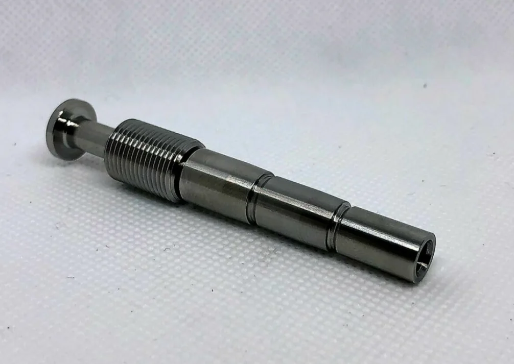
Separate functional diameters, bearing or mating fits, sealing surfaces, threaded features, and ordinary clearance surfaces. Applying very tight size, runout, cylindricity, coaxiality, and roughness requirements to every diameter can add finishing passes, specialized measurement, tool changes, and scrap risk without improving performance.
Geometric tolerances also need a meaningful datum system. A strict runout value without a functional axis or datum may be difficult to interpret and inspect. Discuss assembly and measurement intent during DFM review when the drawing does not clearly communicate it.
Define Material and Inspection Requirements in the RFQ
A useful titanium turning RFQ should state:
- Titanium grade, specification, condition, and acceptable equivalents;
- Required material certification and lot traceability;
- Critical diameters, datums, runout, coaxiality, and surface finish;
- Thread standard, class, inspection method, and any gauging requirement;
- Quantity, annual demand, prototype or production status, and delivery schedule;
- FAI, inspection report, CMM report, or industry documentation requirements;
- Any restrictions on stock form, heat treatment, coolant, cleaning, or finishing.
Complete information allows a supplier to plan tooling, workholding, inspection, and material procurement accurately. It also makes quotations from different manufacturers easier to compare.
How Should You Evaluate a Supplier for Titanium Turning?
Check Experience with Similar Titanium Parts
Do not ask only whether a manufacturer has machined titanium. Confirm experience with the specified grade, similar stock form, comparable diameter and length-to-diameter ratio, and the required operations. A supplier experienced in simple Grade 2 external diameters may not be prepared for Grade 5 deep boring, thin-wall sleeves, close-tolerance threads, or ultra-precise runout.
Ask for a description of relevant process capability without requiring the manufacturer to disclose another customer's confidential drawing. The response should demonstrate an understanding of the geometry, tooling, chip control, inspection, and material-documentation risks in your project.
Match Precision Capability to the Component
General industrial titanium components, medium- and high-precision instrument parts, and ultra-high-precision aerospace, optical, or scientific parts require different resources. Evaluate the tolerances the supplier routinely controls, not only the smallest tolerance shown in a marketing document.
Confirm access to the inspection equipment required for the drawing. Depending on the component, this may include micrometers, bore gauges, thread gauges, surface-roughness testers, CMMs, roundness instruments, or dedicated runout fixtures. The supplier should also have a clear process for first-piece inspection, in-process measurement, tool-offset control, and final reporting.
Review Titanium Process Control
A capable supplier should be able to explain how it plans to manage the major turning risks. Useful questions include:
- How will inserts and chipbreakers be selected for each operation?
- How will tool life be monitored before edge failure affects the part?
- How will long chips and chip recutting be controlled?
- Can coolant be directed effectively into bores and grooves?
- How will thin walls, slender shafts, or deep bores be supported?
- How will heat, springback, unclamping distortion, and size drift be verified?
The objective is not to dictate the supplier's exact proprietary process. It is to confirm that the quotation reflects the actual challenges instead of a generic assumption that all titanium parts are equivalent.
Verify Quality Records and Communication
Before quoting, a responsible supplier may ask questions about grade, condition, datums, inspection, appearance, certification, and quantity. Questions are not necessarily a sign of limited capability; they often show that the manufacturer is identifying risk before production.
Review how drawing revisions, technical clarifications, nonconformities, and inspection records will be communicated. For repeat orders, confirm how material lots, tool changes, process revisions, and corrective actions are recorded. Titanium components can be expensive before machining begins, so communication failures create significant avoidable risk.
How Does RapidMFGPro Help You Find a Titanium Machining Supplier?
Find Manufacturers Experienced in Custom Titanium Machining
RapidMFGPro helps buyers find manufacturers familiar with custom titanium machining instead of sending every titanium request to the same type of supplier. The matching review can consider the specified titanium grade and condition, turning and secondary operations, part geometry, quantity, tolerance, surface requirements, certification, and delivery needs.
This is important because titanium capability is operation-specific. A project involving external turning and a standard thread does not require the same manufacturing resources as a thin-wall Grade 5 sleeve, a deep precision bore, a long shaft, or a component requiring turning, 5-axis milling, finishing, and complete inspection documentation.
Match Manufacturers to Different Industries and Precision Levels
RapidMFGPro has access to a broad pool of reliable manufacturing resources. Supplier selection can therefore reflect the field, application, and precision level of the component, including general industrial requirements, medium- and high-precision parts, and ultra-high-precision projects.
The review can also consider industry-related expectations for aerospace, titanium medical parts, optical, scientific-instrument, automotive, energy, and other applications. The goal is not to claim that every listed manufacturer is suitable for every industry. It is to identify resources whose equipment, engineering experience, inspection capability, quality system, capacity, and documentation are aligned with the submitted project.
Review Supplier Qualifications Before Matching
RapidMFGPro reviews supplier qualifications against the actual project rather than relying only on a general statement that a manufacturer can machine titanium. Depending on the RFQ, the review may consider:
- Experience with the specified grade and comparable titanium components;
- CNC turning, turn-mill, milling, grinding, and secondary-process capability;
- Control of dimensional tolerance, geometric accuracy, and surface finish;
- Inspection equipment, quality procedures, and relevant certifications;
- Capacity for prototypes, low-volume work, or repeat production;
- Delivery performance and technical communication responsiveness.
This qualification review helps reduce the risk of reaching an attractive price first and discovering later that the supplier lacks the appropriate equipment, measurement method, documentation, or titanium experience.
Receive a Suitable Match in Typically 1–2 Business Days
Once the buyer provides drawings and essential requirements, RapidMFGPro can typically complete an initial project review and identify a suitable supplier within one to two business days. Providing the titanium grade, quantity, tolerance, certification, finishing, inspection, and delivery information at the beginning helps accelerate the process.
Projects involving rare titanium grades, ultra-high precision, unusual regulatory documentation, incomplete drawings, or multiple complex processes may require additional review. The one-to-two-day period is therefore a typical matching time rather than an unconditional deadline for every RFQ.
Avoid Hidden or Unjustified Matching Charges
RapidMFGPro keeps the supplier-matching process transparent and focused on the buyer's experience. Buyers will not encounter hidden or unjustified matching charges. Any relevant service terms are communicated clearly before the buyer makes a decision.
After a suitable manufacturer is identified, the buyer can communicate directly with the manufacturer about drawings, quotations, technical questions, lead time, and production arrangements. This helps the buyer evaluate the manufacturing proposal directly instead of receiving only a simplified platform response.
Report an Unsuitable Supplier for Further Review
If a matched supplier does not meet expectations, the buyer can report the issue to RapidMFGPro. Relevant feedback may include a mismatch between stated and actual capability, slow or unclear communication, nontransparent quotation terms, quality concerns, unrealistic delivery commitments, or inaccurate qualification information.
RapidMFGPro will review the reported situation and reassess the supplier where appropriate. If the original match is not suitable, the project requirements and matching result can be reviewed again. Serious or repeated concerns may lead to stricter examination of the supplier. This feedback mechanism helps protect the current buyer and improves the reliability of future matches.
RapidMFGPro helps buyers move from a general request for “a titanium supplier” to a more relevant manufacturing match based on material, geometry, operation, tolerance, inspection, industry, and delivery needs. It is especially useful when the buyer requires a manufacturer with proven custom titanium experience but does not want to spend days contacting and screening factories individually.
FAQ About Turning Titanium
What Is a Good Starting Speed for Turning Titanium?
A good starting speed should be selected in SFM or m/min from the current tool manufacturer's data for the exact titanium grade, insert grade, coating, operation, and coolant condition. Convert that speed to RPM using the current cutting diameter. Do not use one fixed RPM for Grade 2, Grade 5, external turning, boring, and additively manufactured titanium. Begin conservatively, inspect the edge and chips, and adjust using documented tool wear, surface quality, spindle load, and dimensional results.
Should You Take Light or Heavy Cuts When Turning Titanium?
The choice is not simply “light and fast” or “heavy and slow.” The insert needs enough feed and depth to form a stable chip and avoid rubbing, but the load must remain within the limits of the tool, component, workholding, and machine. Rigid roughing often benefits from decisive engagement, while thin walls, slender shafts, finishing cuts, and extended boring bars require lower cutting pressure. Keep the parameters inside the selected chipbreaker's effective range.
Why Does a Titanium Turning Insert Keep Chipping?
First distinguish gradual wear from sudden edge chipping. Sudden damage often indicates chatter, chip recutting, interrupted engagement, excessive tool overhang, poor insert seating, or inadequate workholding. During boring, also check chip packing and whether coolant reaches the cutting edge. Reducing speed helps only when thermal load is the main cause; it will not correct a flexible bar, uncontrolled chips, an off-center tool, or unsuitable geometry.
Conclusion
Titanium turning should not be reduced to “lower the RPM.” Reliable results come from matching the titanium grade, insert geometry, cutting speed, feed, depth of cut, coolant, chip control, and setup rigidity. When an insert chips, the finish deteriorates, or dimensions drift, identify the actual failure mode before changing the process. For buyers, the key is not finding a supplier that generally claims to machine titanium, but verifying experience with a similar grade, geometry, turning operation, precision level, and inspection requirement. RapidMFGPro can shorten this evaluation by matching the project with appropriately qualified manufacturing resources.
Need Help Reviewing a Custom Part?
Share your CAD file and requirements to request supplier matching. Supplier capability and commercial terms must be verified before order placement.
Request Supplier Match