Time to read: 5 min
What Is a Chamfer? Types, Uses, Drawings, and CNC Machining Guide
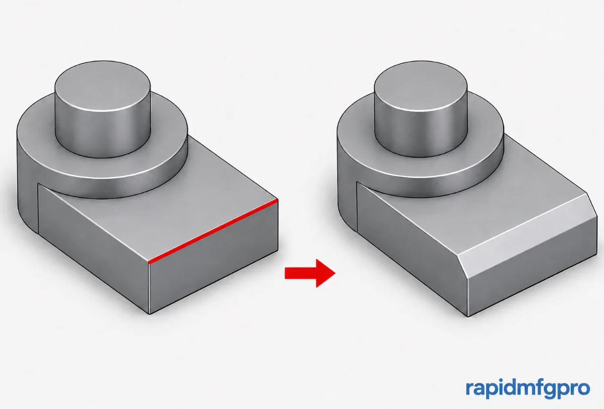
A chamfer is a flat, angled surface created by removing a sharp edge or corner from a part. It is most commonly machined at 45°, but 30°, 60°, and other angles can be used when assembly, clearance, thread entry, appearance, or other functional requirements demand them. Chamfers appear on external edges, holes, shafts, threads, gears, housings, and many other manufactured features.
In CNC machining, a chamfer may be as simple as a small edge break or as important as a controlled assembly feature. That distinction matters. An accessible 45° chamfer may add very little machining effort, while a tightly toleranced internal or back-side chamfer can require special tooling, another setup, and additional inspection.
| Feature | Geometry | Typical Purpose | Typical Drawing Definition |
|---|---|---|---|
| Chamfer | Flat angled surface | Lead-in, edge protection, controlled edge removal | Distance × angle |
| Fillet / Radius | Curved transition | Stress reduction, smooth transition | Radius |
| Break Edge | Small, less precisely controlled edge removal | Remove dangerous sharpness | General note or permitted edge range |
| Countersink | Conical recess around a hole | Seat a countersunk fastener | Diameter/depth and included angle |
| Taper | Gradual dimensional change over a length | Alignment, locking, fit, or sealing | Angle, taper ratio, or end diameters |
What Is a Chamfer in Engineering?
A chamfer is created by removing material from the intersection of two surfaces to form a straight sloped face. When two surfaces originally meet at 90° and equal amounts of material are removed from both sides, the resulting chamfer angle is 45°.
For example, an engineering drawing may specify:
- 0.5 × 45°
- 1 × 45°
- 1 × 30°
- A distance plus a defined angle
- Two unequal distances for an asymmetric chamfer
The word “chamfer” therefore describes the geometry rather than one universal size or angle. A 45-degree chamfer is common because it is simple to define and matches widely available cutting tools, but the appropriate angle should ultimately depend on what the feature needs to do.
What Is the Purpose of a Chamfer?
Chamfers Make Parts Easier to Assemble
One of the most important purposes of a chamfer is creating a lead-in between mating components. Without a lead-in, a pin, shaft, fastener, or bushing may need to be aligned very closely with the mating feature before insertion can begin.
The angled surface can guide one component toward another and tolerate a small amount of initial misalignment. Common applications include:
- Dowel pins entering locating holes
- Shafts entering bushings or bearings
- Fasteners entering clearance holes
- Connectors entering housings
- Bushings being installed into bores
- Components used in automated assembly
However, a larger chamfer does not automatically produce a better assembly feature. Increasing chamfer length removes part of the full-diameter mating surface. On a dowel hole, bearing seat, or interference-fit feature, that may reduce useful locating or engagement length.
The lead-in should therefore be designed together with the mating geometry instead of being added as an independent cosmetic feature.
Chamfers Help Threads Start Correctly
Internal and external threads commonly use an entrance chamfer. The chamfer removes a vulnerable sharp edge and gives the mating screw or nut a more forgiving starting condition.
On a tapped hole, a chamfer can also remove burrs around the hole entrance and prevent an incomplete first thread from interfering with assembly. On an external thread, a lead chamfer helps a nut start without immediately catching on the thread crest.
There is also a limit. An oversized entrance chamfer can consume useful thread engagement, especially in shallow blind holes where the available full-thread depth is already restricted.
Chamfers Remove Sharp Edges
Freshly machined aluminum, stainless steel, steel, titanium, and other materials can have extremely sharp edges even after loose burrs have been removed.
A small chamfer can make the part safer to handle and reduce the possibility of an edge:
- Cutting an operator
- Damaging a cable or wire
- Scratching a mating component
- Tearing packaging
- Damaging a seal during installation
For a purely non-functional edge, however, a precisely dimensioned chamfer may not be necessary. A controlled edge-break requirement can sometimes provide the needed handling safety with less machining and inspection burden.
Chamfers Protect Vulnerable Corners
A perfectly sharp external corner has very little supporting material at its extreme edge. It can be dented, rolled, chipped, or damaged during machining, handling, shipping, assembly, or later service.
Removing the knife edge with a small chamfer gives the corner more practical durability without significantly changing the overall geometry.
Chamfers Can Improve Appearance
Chamfers are also used deliberately as visible design features. A consistent angled edge can create a more controlled transition around:
- Machined housings
- Electronic enclosures
- Knobs and controls
- Panels
- Consumer products
- Decorative machined components
Cosmetic chamfers often need more consistency than an ordinary deburred edge because changes in chamfer width can become especially visible after anodizing, plating, polishing, brushing, painting, or other surface treatments.
Do Chamfers Reduce Stress Concentration?
A chamfer can reduce the severity of a perfectly sharp geometric transition by removing the abrupt corner. However, this point is often oversimplified.
A chamfer is not automatically the best geometry for a fatigue-critical transition. A radius or fillet creates a smoother change in section and may produce better stress distribution when cyclic loading or structural fatigue is the dominant design concern.
Where stress concentration is important, compare the chamfer with an appropriate radius rather than assuming the two features are mechanically equivalent. See RapidMFGPro's guide to fillet and corner radius selection for CNC-machined parts.
What Types of Chamfers Are Common?
| Chamfer Type | Definition | Common Use | Manufacturing Consideration |
|---|---|---|---|
| Equal 45° Chamfer | Equal setback from two perpendicular surfaces | General edges, holes, shafts | Usually one of the simplest options to machine |
| Distance-Angle Chamfer | One linear distance plus a specified angle | Assembly and clearance features | May require a different cutter angle |
| Two-Distance Chamfer | Different setbacks on the two adjoining surfaces | Asymmetric geometry | Usually programmed directly from CAD geometry |
| Hole Chamfer | Angled entrance or exit around a hole | Pins, tapping, fasteners, burr removal | Front-side and back-side accessibility may differ greatly |
| Thread Chamfer | Lead treatment at a thread entrance | Improve thread starting | Must preserve enough usable thread engagement |
| Shaft-End Chamfer | Angled edge around a cylindrical end | Bearing, bushing, seal, and assembly lead-in | Often produced directly during CNC turning |
| Gear Chamfer | Controlled removal around gear or tooth edges | Edge protection and assembly | High-volume applications may use dedicated equipment |
| Custom Chamfer | Unusual or compound angled geometry | Special functional or cosmetic requirements | May require special tooling or multi-axis machining |
45-Degree Chamfer
The 45° chamfer is the most familiar type. On a 90° corner, equal material removal from both adjoining surfaces naturally produces a 45° face.
It is commonly used on external edges, shaft ends, holes, threads, and general assembly lead-ins.
Distance-and-Angle Chamfer
A chamfer does not have to remove equal material from both surfaces. Designers can define a distance from one surface and then specify an angle such as 30° or 60°.
This approach is useful when the angle itself influences component guidance, clearance, or mating behavior.
Two-Distance or Asymmetric Chamfer
An asymmetric chamfer uses different setbacks on its two adjacent faces. This may be required when one side has limited available material or when the geometry must transition toward a specific mating feature.
It may also be less convenient to manufacture than a standard 45° feature because the required cutter geometry may not correspond directly to a standard chamfer mill.
Hole Chamfer
Hole entrances are among the most common places where chamfers are used. A hole chamfer can:
- Remove a drilling burr
- Guide a pin or fastener
- Prepare the entrance before tapping
- Protect a mating component
- Create a controlled visual edge
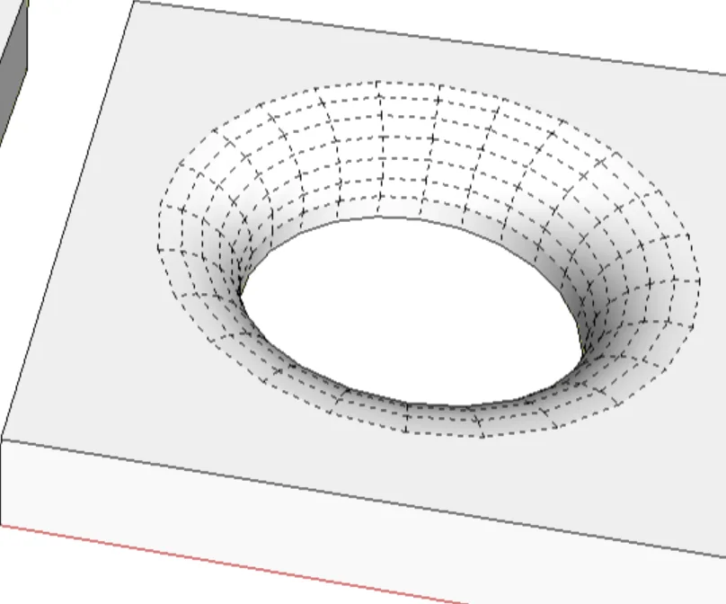
A through hole may also need its back-side edge chamfered. This is where manufacturing complexity can change considerably because the second edge may not be directly accessible in the same setup.
Shaft-End Chamfer
Shafts, pins, bushings, sleeves, spacers, and similar rotational components frequently use chamfers on their ends.
These features can help the part enter a bearing, bore, bushing, seal, or other mating component without damaging the adjacent edge.
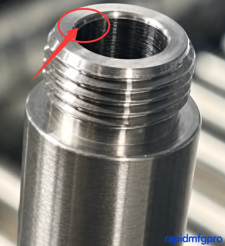
Thread Chamfer
A thread chamfer creates a lead at the beginning of a thread. The geometry should be large enough to support reliable engagement but not so large that it unnecessarily removes usable threaded length.
Gear Chamfer
Gear edges and tooth edges may be chamfered to remove sharpness, improve handling and assembly, and reduce susceptibility to edge damage.
Depending on production quantity and geometry, gear chamfering may be performed with conventional CNC tools or specialized high-volume chamfering equipment.
Chamfer vs Bevel vs Fillet vs Taper: What Is the Difference?
Chamfer vs Bevel
Chamfer and bevel terminology overlaps considerably.
In precision machining, “chamfer” commonly describes a relatively short and controlled angled edge. “Bevel” is often used for a larger angled surface, plate edge, weld preparation, or structural feature.
However, this distinction is not applied consistently across every industry. If geometry affects fit, inspection, or function, specify the actual dimensions and angle instead of relying only on the word “bevel.”
Chamfer vs Fillet or Radius
A chamfer consists of a straight angled surface, while a fillet or radius is curved.
Chamfers are commonly selected for:
- Assembly lead-ins
- Thread entrances
- Controlled edge removal
- Simple cosmetic transitions
Radii are commonly preferred for:
- Stress-sensitive transitions
- Fatigue-critical shoulders
- Smooth ergonomic corners
- Curved design transitions
You may encounter the expression “R-chamfer” in some tooling catalogs or shop terminology, but if the geometry is actually curved, a production drawing should identify the radius clearly rather than treating it as an ordinary straight chamfer.
Chamfer vs Taper
A taper gradually changes diameter or width over a meaningful length of the component. Chamfers are localized edge features.
Tapers are commonly used for:
- Alignment
- Self-locking mechanical interfaces
- Machine-tool connections
- Sealing
- Controlled mating fits
A Morse taper, for example, should not be considered simply a very large chamfer. Its gradual dimensional change performs a specific fitting and locating function.
Chamfer vs Countersink
A countersink is a conical recess around a hole, most commonly designed to seat a countersunk fastener.
A chamfered hole may appear similar, but its purpose may simply be:
- Removing a sharp hole edge
- Guiding a pin
- Creating a thread lead-in
- Removing drilling burrs
If a flat-head screw must sit flush, specify the countersink geometry required by the fastener instead of assuming a generic hole chamfer will produce the correct seat.
Chamfer vs Break Edge vs Deburring: Are They the Same?
No. The difference is mainly the amount of geometric control required.
Deburring removes unwanted material left by cutting, drilling, milling, turning, grinding, or other manufacturing operations. The final edge does not necessarily have a precise width or angle.
Breaking an edge intentionally removes sharpness, but the final geometry may still have considerable manufacturing freedom depending on the drawing requirement.
A dimensioned chamfer is an intentional measurable feature with a defined size and, where necessary, a controlled angle.
This distinction matters directly during CNC quoting.
For example:
- “Deburr all edges” primarily asks the manufacturer to remove unwanted burrs.
- “Break sharp edges” requests a controlled safe edge but may allow some geometric variation.
- “0.5 × 45°” defines a measurable chamfer feature.
If assembly depends on the chamfer width or angle, do not replace the dimension with a generic deburring note.
Likewise, do not assume that an unspecified CAD edge will automatically receive a particular chamfer size. If an edge must remain sharp for cutting, metering, scraping, optical, fluid-control, or another functional reason, state that requirement clearly.
How Should You Choose Chamfer Size and Angle?
There is no universal “best” chamfer size. The design should begin with the function of the edge.
- Handling edge: remove only enough material to eliminate unsafe sharpness.
- Assembly lead-in: relate the chamfer to mating clearance and expected initial misalignment.
- Dowel or locating hole: preserve enough cylindrical length for accurate location.
- Press-fit feature: create a useful lead-in while maintaining sufficient full-diameter interference length.
- Thread entry: provide enough guidance without consuming excessive usable thread engagement.
- Seal installation: protect the seal during insertion without removing required sealing support.
- Cosmetic edge: choose a size that can be reproduced consistently after machining and finishing.
- Structural transition: evaluate whether a radius is more appropriate than a chamfer.
Does a Larger Chamfer Always Make Assembly Easier?
A larger lead-in can accommodate more initial misalignment, but it also removes more mating surface.
Consider a shaft entering a precision bore:
Increasing the chamfer may make the first contact easier, but the larger chamfer also shortens the length of full-diameter bore available for guidance. On a bearing, dowel, bushing, or press fit, that tradeoff may matter.
The goal should therefore be the smallest chamfer that reliably performs the required assembly function rather than the largest chamfer that physically fits.
How Should You Specify a Chamfer on an Engineering Drawing?
Use Distance and Angle When Geometry Matters
A notation such as:
0.5 × 45°
communicates both the linear size and angle of the chamfer.
If the design uses a non-45° chamfer, state the angle instead of expecting the supplier to infer it.
What Does C1 Chamfer Mean?
Shorthand such as C0.5, C1, and similar callouts is widely encountered in manufacturing drawings. Under drawing conventions where “C” indicates a 45° chamfer, C1 typically represents a 1 mm chamfer.
However, company and regional drawing practices are not completely universal. For an international manufacturing RFQ, explicitly stating 1 × 45° removes unnecessary ambiguity when the angle is important.
Use a General Edge Note When Exact Geometry Does Not Matter
If an edge only needs to be safe to handle, individually tolerancing every chamfer can create manufacturing work without improving the part.
A controlled general edge-break requirement may be more appropriate. Conversely, if assembly, fit, appearance, or inspection depends on the edge, give it an explicit dimension.
This distinction is also reflected in ISO 13715:2017 — Edges of undefined shape. The standard addresses the indication and dimensioning of edges where the exact final geometry is not defined. When a geometrically defined feature such as a 1 × 45° chamfer is required, the specific geometry should instead be dimensioned explicitly.
Do the CAD Model and Drawing Need to Show Every Chamfer?
Functionally important and relatively large chamfers should normally be represented clearly in the model or drawing because they influence fit, CAM programming, inspection, or appearance.
Very small non-critical edge breaks can sometimes be controlled with a general drawing note instead of modeling every single edge.
The important requirement is consistency.
If:
- The CAD model shows a sharp edge but the drawing specifies a chamfer
- The model contains a chamfer that is absent from the drawing
- Different files give different chamfer dimensions
the manufacturer needs a clear rule establishing which requirement controls production.
An unimportant CAD edge should not become a cause of part rejection simply because the model and drawing were not coordinated.
How Are Chamfers Made?
CNC Milling
Chamfer mills and other angled cutters can follow external edges, pocket contours, and hole entrances on a CNC milling machine.
Simple accessible chamfers can often be machined during the same setup as the other features of the part.
For housings, brackets, plates, blocks, and other prismatic components, CNC milling allows chamfers to be integrated directly into the programmed toolpath.
CNC Turning
On shafts, pins, sleeves, bushings, rings, and other rotational components, chamfers are commonly produced using the normal turning tool and programmed X/Z movement.
Shaft-end chamfers, bore entrances, shoulders, and thread leads can frequently be machined without introducing a completely separate operation.
These features are common in precision CNC turning because they can often be created within the same setup as the adjacent diameters and faces.
Hole Chamfering
Several tools can create a hole-entry chamfer, including:
- Chamfer mills
- Countersink cutters
- Spot drills
- Combination drill-chamfer tools
- Front-and-back chamfering tools
Tool selection depends on the required angle, hole size, accessibility, tolerance, material, and production volume.
Manual Chamfering
Manual methods include:
- Files
- Scrapers
- Carbide burrs
- Abrasive wheels
- Handheld deburring tools
These methods can be appropriate for prototypes, repair work, difficult-to-access edges, and general edge breaking.
They become less attractive when the chamfer needs a tightly controlled dimension or must remain visually consistent across a large batch.
Dedicated and Automated Chamfering
High-volume gear, bar, tube, and production applications may use dedicated chamfering machines instead of general-purpose CNC milling or turning.
Automating the operation can improve repeatability and cycle time when thousands of similar edge features need to be produced.
What Is a Chamfer Mill?
A chamfer mill is an angled cutting tool designed to machine chamfers, hole-edge features, V-grooves, deburring features, and related angled surfaces.
Common angles include 30°, 45°, and 60°, although many other geometries are available.
Selecting a chamfer mill involves more than simply matching the nominal angle. The machinist may also consider:
- Required chamfer width
- Internal or external access
- Hole diameter
- Workpiece material
- Tool diameter
- Tool rigidity
- Number of cutting edges
- Tool-point geometry
- Holder clearance
- Surface-finish requirement
- Production quantity
The relationship between programmed tool depth and actual chamfer width also depends on the real cutter geometry.
For example, some chamfer mills do not come to a theoretical sharp point. If the tool has a small flat at the tip, calculating chamfer size from the nominal angle alone may introduce an error.
For a precision feature, a machinist may make a test cut, measure the chamfer, and adjust the tool offset before final production.
Why Do Chamfers Chatter or Become Uneven?
Chamfering may look like a minor finishing operation, but a relatively wide chamfer can create substantial radial cutting forces.
Chamfer Chatter
Possible causes of chatter include:
- Excessive chamfer width
- Large tool engagement
- Excessive tool overhang
- Insufficient tool or holder rigidity
- Unfavorable spindle speed
- Poor cutter geometry for the material
- Weak workholding
- Machine or tool resonance
A large chamfer does not simply mean removing slightly more material. The additional cutter engagement can significantly increase cutting force and chatter risk.
Possible solutions include improving tool rigidity, reducing overhang, changing cutting conditions, using a more suitable cutting geometry, reducing the amount removed per pass, or changing the toolpath strategy.
Uneven Chamfer Width
If one section of a chamfer is wider than another, possible causes include:
- Tool deflection
- Tool wear
- Runout
- Incorrect Z offset
- Fixture movement
- CAM toolpath errors
- Machine positioning error
- Variation in the incoming part geometry
This is why chamfer accuracy does not depend on the cutting tool alone. The machine, holder, fixture, tool condition, programming, workpiece geometry, and material all contribute to the finished result.
Burrs After Chamfering
Chamfering is often used to remove burrs, but the operation can also generate a secondary burr if the cutting conditions are poor.
Possible causes include:
- Dull cutting edges
- Incorrect feeds and speeds
- Poor chip evacuation
- Re-cutting chips
- Difficult or gummy materials
Why Are Back-Side Chamfers More Difficult?
A chamfer on the top side of an accessible hole may take only seconds to produce. An identical 0.5 × 45° chamfer on the far side of the same hole can require a completely different manufacturing approach.
The supplier may need:
- A back-chamfering tool
- An additional part setup
- 4-axis or 5-axis repositioning
- Manual secondary finishing
- A custom tool
Two chamfers that look identical on a drawing can therefore have very different manufacturing costs because tool access is different.
How Does Material Affect Chamfer Machining?
| Material | Typical Chamfering Behavior | Design / Manufacturing Consideration |
|---|---|---|
| Aluminum | Generally machines efficiently, but soft edges can burr or show visible variation | Control cosmetic chamfers carefully before anodizing |
| Stainless Steel | Can produce higher cutting forces and greater tool wear depending on grade | Avoid unnecessarily tight tolerances on non-functional chamfers |
| Titanium | Heat concentration and tool wear require more process control | Keep precision chamfers purposeful and accessible |
| Engineering Plastics | Some materials smear, deform, or form soft burrs | Very small cosmetic chamfers can be difficult to reproduce cleanly |
| Hardened Metals | Higher tool wear and cutting load | Tool selection and chamfer width have greater cost impact |
The same chamfer geometry does not necessarily have the same manufacturing difficulty in aluminum, stainless steel, titanium, hardened steel, and plastic.
Material properties influence:
- Tool wear
- Burr formation
- Cutting force
- Heat generation
- Surface finish
- Practical cutting speed
This is another reason why finished machining cost cannot be estimated from chamfer dimensions alone.
How Are Chamfers Measured and Inspected?
The inspection method should match the functional importance of the chamfer.
Visual Inspection
For general edge breaks, visual inspection may be sufficient to confirm that burrs and dangerous sharpness have been removed.
Chamfer Gauge
Chamfer gauges can provide quick production measurements for compatible internal or external chamfer geometries.
Optical Comparator or Vision Measurement
Optical systems can be useful for small profiles where the angle and width need to be measured without physically contacting a delicate feature.
CMM Inspection
A coordinate measuring machine may be used when the chamfer is part of a high-precision feature, inspection traceability is required, or the adjacent geometry makes manual measurement difficult.
Functional Inspection
Sometimes the real requirement is not the nominal chamfer dimension itself but whether the mating component installs correctly.
A functional gauge, representative pin, shaft, fastener, or mating component may therefore provide more relevant information than measuring a non-critical cosmetic edge to an unnecessarily tight tolerance.
When Should You Avoid a Chamfer?
When Maximum Contact Area Is Required
A large chamfer can remove useful area from a bearing, locating, clamping, or load-bearing surface.
A small lead-in may still be helpful, but it should not consume the contact area required by the design.
On Certain Press-Fit Features
A press fit often benefits from a lead-in because it reduces the chance of damaging the edge during insertion.
However, excessive chamfer length reduces the full-diameter interference zone. The design therefore needs to balance assembly guidance with effective engagement length.
On Certain Sealing Interfaces
Some seals require a controlled lead-in chamfer so that the seal is not cut during installation. The actual sealing land, however, must remain intact.
A random chamfer on a precision sealing face can reduce required contact area rather than improve the design.
Where a Sharp Edge Is Functional
Some features intentionally need sharp or specifically controlled edges, including:
- Cutting edges
- Scraper edges
- Metering edges
- Some valve features
- Optical apertures
General instructions such as “chamfer all edges” can make these components non-functional.
On Very Thin Features
A chamfer can remove a significant portion of a thin wall or flange if its size is large relative to the remaining material thickness.
Where a Radius Is Better for the Load Path
If fatigue resistance and gradual stress transfer are the primary objectives, compare the design with a suitable radius rather than assuming that a flat chamfer offers equivalent structural behavior.
How Much Does a Chamfer Add to CNC Machining Cost?
A small, accessible, standard chamfer can have very little impact on finished part cost, especially when it can be machined in the existing setup using a tool already loaded in the machine.
Cost increases when the chamfer creates additional manufacturing requirements.
| Cost Driver | Why It Matters | DFM Approach |
|---|---|---|
| Non-Standard Angle | May require another cutter or machining operation | Use standard angles where function allows |
| Difficult Access | Can require back tools, 5-axis positioning, or another setup | Review edge accessibility before releasing CAD |
| Tight Tolerance | Adds tool control and inspection effort | Tighten only functional chamfers |
| Large Chamfer Width | Increases tool engagement and chatter risk | Use only the size required by function |
| Many Different Chamfers | Adds programming, tools, offsets, and inspection variation | Standardize repeated non-critical features |
| Difficult Material | Can increase tool wear and cycle time | Match tooling and tolerance to material behavior |
| Back-Side Feature | May create secondary operations | Evaluate back-chamfer tools or redesign where practical |
Raw material removed by a chamfer is tiny, but that does not determine its real manufacturing cost.
The more useful cost equation is:
Chamfer Cost = Tooling + Machine Time + Tool Changes + Setup Time + Tool Wear + Inspection + Secondary Operations
For example, adding a 0.5 mm chamfer to an accessible top edge may have almost no practical impact on the quote. Adding the same 0.5 mm chamfer beneath an internal shoulder may require another setup or a special tool.
This is why DFM should focus on the complete manufacturing process rather than the amount of material being removed.
What Are the Most Common Chamfer Design Mistakes?
Assuming Every Sharp CAD Edge Should Be Chamfered
Manufacturers generally remove dangerous burrs, but designers should not depend on an unwritten assumption for functional edge geometry.
Specify important chamfers and clearly identify edges that intentionally need to remain sharp.
Using “Deburr” When a Controlled Lead-In Is Required
Deburring does not guarantee a specific angle or width.
If a shaft, pin, seal, fastener, or thread depends on the entrance geometry, dimension the chamfer.
Making Every Chamfer a Precision Feature
If 30 non-functional edges each receive individual tight chamfer tolerances, the supplier may need to treat all 30 as measurable production characteristics.
This can increase programming, adjustment, inspection, and documentation without improving how the part functions.
Forgetting That a Chamfer Removes Engagement Length
A large chamfer may make initial insertion easier while reducing:
- Press-fit length
- Dowel locating length
- Bearing engagement
- Thread engagement
- Sealing support
Ignoring the Back Side of a Through Hole
If both sides need burr removal, state the requirement clearly.
If only one side has a precision functional chamfer, distinguish it from the opposite edge. Otherwise, the manufacturer may reasonably use different edge-finishing methods on each side.
Ignoring Tool Access
A chamfer located underneath a shoulder, deep inside a bore, or on the far side of an internal feature may be much more difficult to reach than an identical feature on an exposed edge.
Assuming the Cutter Automatically Guarantees Chamfer Accuracy
The final dimension can still be influenced by:
- Tool deflection
- Runout
- Cutter-tip geometry
- Tool wear
- Fixture rigidity
- Z offsets
- Material variation
- Machine positioning
Where Are Chamfers Used?
Chamfers are found across manufacturing because the same simple angled geometry can perform several different functions.
- Shafts and pins: assembly lead-ins and edge protection
- Threaded components: improved thread starting
- Gears: tooth-edge and component-edge protection
- Aerospace components: controlled fastener-hole and assembly geometry
- Automotive parts: shafts, housings, bores, grooves, and assembly interfaces
- Molds and tooling: mating features and controlled transitions
- Consumer electronics: visible machined edges and handling comfort
- Industrial equipment: assembly guidance and handling protection
- Fabricated components: selected edge preparation and safe handling
The key point is that these features do not all require the same tolerance.
A cosmetic enclosure chamfer, a gear chamfer, a thread lead-in, and a precision dowel-hole entrance may all appear as angled surfaces, but their functional importance and inspection requirements can be completely different.
Chamfer DFM Checklist Before Sending a CNC RFQ
- Identify which chamfers are functional, cosmetic, or only intended to remove sharpness.
- Specify size and angle for functional chamfers.
- Check mating components before choosing lead-in dimensions.
- Confirm enough locating, bearing, press-fit, sealing, or thread engagement remains.
- Use standard angles where no functional requirement demands a special angle.
- Standardize repeated non-critical chamfers when practical.
- Avoid unnecessarily tight chamfer tolerances.
- Check cutter access to internal and back-side edges.
- Identify any edges that must intentionally remain sharp.
- Consider how anodizing, plating, polishing, or other finishing will affect visible edges.
- Define the inspection requirement for critical chamfers before production begins.
How RapidMFGPro Helps With Chamfered CNC Parts
Chamfer requirements demonstrate why a CNC supplier should be evaluated against the actual part rather than only a generic machine list.
A manufacturer capable of producing an ordinary external 45° chamfer may not automatically be the right supplier for a part containing:
- Deep internal chamfers
- Back-side hole chamfers
- Large chamfers susceptible to chatter
- Titanium or other difficult materials
- Multi-axis access requirements
- Tightly controlled cosmetic chamfers
- High-precision inspection requirements
RapidMFGPro helps buyers identify independent manufacturers according to the complete production requirement, including material, geometry, tolerance, production quantity, milling or turning process, edge accessibility, surface finishing, and inspection needs.
For example, a turned shaft with straightforward end chamfers may be best matched with an experienced precision turning supplier. A housing containing controlled chamfers on several orientations may be easier to manufacture with multi-axis milling. A small back chamfer deep inside a precision bore may require a supplier with specialized tooling and inspection capability.
RapidMFGPro can also help buyers distinguish between a functional chamfer and a general edge-break requirement before quotation. That distinction can prevent unnecessary precision from increasing the quote while reducing the risk that an important assembly feature is under-specified.
For projects involving chamfers and other complex machined features, RapidMFGPro's CNC machining supplier matching can connect buyers with manufacturers whose capabilities better fit the actual drawing, material, tolerance, and production requirements.
FAQs About Chamfers
Is a Chamfer Always 45 Degrees?
No. A 45° chamfer is common, but 30°, 60°, and other angles may be used when required by assembly, clearance, tooling, appearance, or another functional condition.
What Does C1 Chamfer Mean?
Under many metric drawing conventions, C1 commonly indicates a 1 mm 45° chamfer. Because drawing conventions can vary, explicitly specifying 1 × 45° is clearer when the angle is important.
What Is a Chamfered Hole?
A chamfered hole has an angled surface around its entrance or exit. The feature may remove burrs, guide a fastener or pin, prepare a thread entrance, or protect the hole edge.
Is a Chamfered Hole the Same as a Countersunk Hole?
No. A countersink creates a defined conical recess, often designed to seat a flat-head screw. A chamfered hole may simply use a small angled edge for deburring or assembly guidance.
Should Every CNC-Machined Edge Have a Chamfer?
No. Burrs and unsafe sharpness generally need to be controlled, but that does not mean every edge requires a precisely dimensioned chamfer. Use dimensioned chamfers where geometry affects assembly, fit, appearance, or another function, and use an appropriate general edge requirement where exact geometry does not matter.
Does a Larger Chamfer Always Make Assembly Easier?
A larger chamfer can provide more initial guidance, but it also removes more mating surface. On press fits, locating holes, bearings, and threaded features, an excessive chamfer can reduce useful engagement. Choose a size based on the complete mating geometry rather than maximizing chamfer width.
Is Chamfering the Same as Deburring?
No. Deburring removes unwanted burrs, while a chamfer is a defined geometric feature. A deburred edge may not have a controlled angle or width.
Can Chamfers Increase CNC Machining Cost?
Yes, although simple accessible chamfers often add little cost. Cost can increase when the feature requires a non-standard tool, tight tolerance, difficult access, another setup, back-side machining, additional inspection, or manual finishing.
Conclusion
A chamfer is a flat angled feature used to replace a sharp edge, commonly for assembly guidance, safer handling, thread entry, edge protection, and controlled appearance. Although 45° chamfers are common, the correct size and angle depend on the actual function rather than a universal rule.
The most important design distinction is whether an edge requires a precise functional chamfer or simply controlled deburring. Chamfer size, tolerance, material, cutter access, setup orientation, and inspection can all affect finished machining cost. Designers should also check whether the chamfer reduces useful fit or thread engagement, whether a radius would better handle structural stress, and whether any edge intentionally needs to remain sharp. A small edge feature can therefore have a meaningful effect on assembly, manufacturability, inspection, and supplier selection.
Need Help Reviewing a Custom Part?
Share your CAD file and requirements to request supplier matching. Supplier capability and commercial terms must be verified before order placement.
Request Supplier Match