Time to read: 4 min
How Can You Reduce CNC Machining Costs Through Better Part Design?
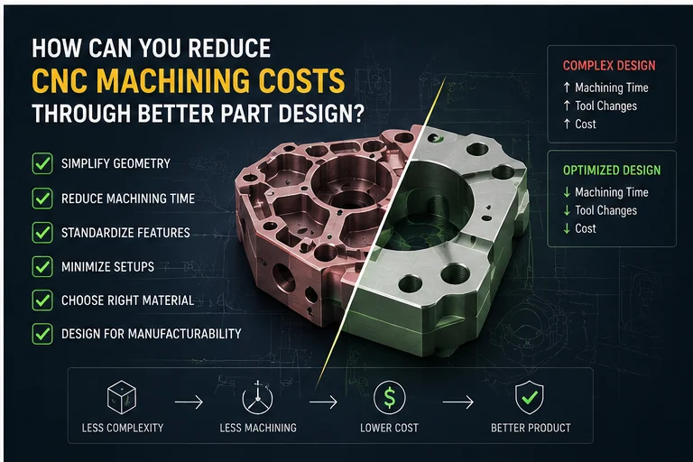
You can reduce CNC machining costs by designing the part to require less machine time, fewer setups, more rigid tooling, simpler workholding, easier inspection, and fewer secondary operations. The goal is not to make every geometry simple or every tolerance loose. It is to preserve the features that control part function while removing manufacturing difficulty that does not provide equivalent engineering value.
A seemingly small CAD change can sometimes alter the entire machining route. Increasing an internal corner radius may allow a larger cutter. Moving two side holes onto the same orientation may remove a setup. Changing a deep blind hole to a through hole can simplify drilling and chip evacuation. Relaxing one noncritical tolerance may remove a finishing or inspection operation. Therefore, instead of asking only whether a part can be machined, ask: which features are actually making this particular CNC part expensive?
| Design Factor | Why It Can Increase CNC Cost | Lower-Cost Design Direction |
|---|---|---|
| Small internal radii | May require smaller cutters, slower machining, and extra tools | Increase and standardize radii where possible |
| Deep pockets | Require longer tools, smaller step-downs, and more cutting time | Reduce depth or improve access |
| Thin walls | Increase deflection, vibration, and distortion risk | Increase stiffness where function permits |
| Features on many sides | Create additional setups and datum transfers | Group features into fewer machining orientations |
| Tight tolerances everywhere | Add finishing, process control, and inspection | Apply tight tolerances only where function requires them |
| Deep blind holes | Make chip evacuation and tool access more difficult | Use through holes when function allows |
| Non-standard holes and threads | May require special or additional tooling | Use common tool sizes where practical |
| Machined text and logos | Add small-tool machining and dedicated toolpaths | Consider simpler marking methods |
| Multiple finishes | Add masking, handling, processing, and inspection | Use one finish where possible |
| Difficult-to-machine materials | Can reduce cutting speed and increase tooling consumption | Compare finished-part cost, not raw material price alone |
What Actually Makes a CNC Machined Part Expensive?
Machining Time Matters More Than How Complicated the CAD Looks
A complicated-looking component is not automatically expensive. What matters is what the geometry forces the machine to do.
A large open pocket may be removed quickly with a rigid cutter, while one small deep slot may require a long, slender end mill, low feed rates, multiple depth passes, careful chip evacuation, and an additional finishing tool. The small feature can therefore contribute more machining time than the large feature.
This is why reducing CNC machining cost requires looking beyond part size or visual complexity. The more useful question is: which feature forces the slowest machining operation?
Setup Time Can Matter as Much as Cutting Time
The machine cannot cut every feature from every direction without changing how the part is held. Before machining, the workpiece must be located, clamped, referenced, and sometimes probed. If the part then needs to be rotated or transferred to another fixture, another setup begins.
Additional setups can involve operator handling, workholding preparation, datum transfer, probing, tool clearance checks, and additional dimensional verification. These costs are especially noticeable for prototypes and low-volume CNC parts because the setup cost is divided across relatively few components.
Inspection Can Become a Hidden Cost Driver
A feature can be relatively easy to machine but surprisingly difficult to inspect. A tightly controlled bore at the bottom of a narrow cavity, for example, may require more measurement effort than an accessible external diameter with a similar numerical tolerance.
For this reason, an economical CNC design should be not only machinable but also economically measurable.
Which Design Change Should You Make First to Reduce CNC Cost?
Many CNC design guides provide long lists of cost-saving tips. The problem is that not every recommendation has the same effect on every part. If you can change only one or two features, start with the features that dominate the manufacturing route.
A useful order for reviewing a CNC part is:
- Extra setups: Can features be reached from fewer orientations?
- Long cycle-time features: Are deep cavities, narrow slots, small radii, or long-reach features slowing machining?
- Special tooling: Does one feature require an unusual cutter, reamer, thread tool, or custom fixture?
- Tight tolerances and inspection: Which requirements create finishing passes or difficult measurement?
- Excessive material removal: Is most of the original stock eventually turned into chips?
- Secondary and cosmetic work: Are multiple finishes, engraved text, exact edge chamfers, or cosmetic requirements necessary?
This prioritization prevents a common DFM mistake: spending time optimizing inexpensive features while leaving the true cost driver untouched.
If a deep pocket contributes several minutes of machining time per part, changing a decorative chamfer may make almost no difference to the final quote. Cost reduction should begin with the machining route, not with whichever CAD feature is easiest to edit.
How Can Internal Corners and Pockets Be Designed for Lower CNC Cost?
Use Larger Internal Corner Radii Where Possible
A milling cutter is round, so an internal milled corner naturally contains a radius. Specifying a very small internal radius can force the manufacturer to use a correspondingly small tool.
Smaller cutters are generally less rigid and remove less material per pass. They may therefore increase machining time, especially when the pocket is also deep.
If the mating geometry does not require a tight internal corner, increasing the radius can allow a larger and more efficient cutter.
Keep Similar Internal Radii Consistent
The number of different radii can matter as well as their size. Imagine a component containing otherwise similar pockets with 3 mm, 3.2 mm, 4 mm, and 5 mm internal radii without any functional reason for the differences.
Even if all four are machinable, the geometry may require more tooling or additional CAM strategies. Standardizing noncritical radii can reduce unnecessary tool changes and simplify programming.
Use Corner Relief When a Mating Part Needs a Square Corner
Sometimes a rectangular mating component needs to sit completely inside a pocket. Specifying an extremely small internal radius is not necessarily the best solution.
Dog-bone or similar corner relief can provide clearance for the mating component while allowing the main pocket to be produced using a larger cutter. This is particularly useful when the exact appearance of the pocket corner is not functional.
Avoid Deep Pockets When Their Full Depth Is Not Functional
Deep cavities often require longer tool extension. As tool reach increases, rigidity decreases and vibration becomes more difficult to control. Chip evacuation also becomes harder, and the manufacturer may need shallower cuts or additional machining passes.
Deep pockets are certainly machinable. The issue is whether their depth justifies the extra machining effort.
If a cavity exists mainly for weight reduction, consider whether shallower pockets, ribs, another starting material form, or a multi-piece construction could provide the required performance with less machining.
Are all of the chamfers in your CAD really necessary? See when a CNC chamfer controls assembly or function and when a simpler edge break may be enough.
How Can You Reduce CNC Setup Costs Through Better Feature Orientation?
Group Features Into Fewer Machining Directions
Consider the direction from which every hole, slot, pocket, groove, and counterbore must be machined. If several noncritical features can share the same orientation, the manufacturer may be able to produce them without repositioning the workpiece.
For example, cross holes located at four unrelated angular positions can create a different manufacturing route from four holes that can all be accessed from one or two orientations.
This does not mean changing a functional orientation purely for manufacturing convenience. It means avoiding orientation differences that serve no engineering purpose.
Keep Related Machined Surfaces at Common Levels Where Practical
Minor differences in surface height can sometimes create additional contouring or finishing operations. If several pads or pocket floors perform the same function and do not need different Z levels, aligning them may allow simpler machining strategies.
Consider Keyways, Grooves, and Cross Holes Together
A turned shaft may be straightforward until several secondary milled features are added at unrelated angular orientations. If keyways, flats, cross holes, or slots can share a logical orientation without affecting assembly, the secondary milling operation may become easier to fixture, index, and inspect.
Why Should CNC Part Designers Think About Workholding?
The Manufacturer Needs Somewhere to Hold the Part
Tool access is only half of the access problem in CNC machining. The workpiece must also remain securely located while the cutter applies force to it.
A design can become expensive when nearly every rigid clamping surface disappears during the first machining operation. The supplier may then need custom soft jaws, sacrificial tabs, vacuum fixtures, special supports, or a more complicated operation sequence.
Ask What Can Be Used for the Next Setup
When reviewing a CNC design, think beyond the final shape and consider how the shape develops during machining:
- Which surface could establish the first datum?
- Where can the raw stock be clamped?
- Which locating surfaces remain after the first operation?
- Can the second setup reference a rigid machined surface?
- Can clamping pressure distort a thin wall?
- Will the fixture block access to another critical feature?
A part that provides stable locating and clamping surfaces can often be manufactured more consistently than one that leaves the supplier with no practical way to hold it after the first operation.
Can 5-Axis CNC Machining Sometimes Cost Less Than Multiple 3-Axis Setups?
Yes. A 5-axis machining center generally has a higher hourly machine rate than a basic 3-axis mill, but machine rate alone does not determine finished CNC part cost.
Suppose a component requires machining on five sides. A 3-axis route may require repeated removal, rotation, reclamping, probing, and datum transfer. A 5-axis machine may be able to access most of those features with significantly fewer setups.
The correct comparison therefore includes:
- machine rate;
- total cutting time;
- number of setups;
- fixture requirements;
- operator intervention;
- datum transfer;
- inspection requirements;
- risk of setup-related variation.
For straightforward prismatic components, 3-axis milling can remain the more economical choice. For complex multi-face parts, however, a higher machine rate may be offset by a shorter and more stable overall manufacturing route.
Why Do Thin Walls and High-Aspect-Ratio Features Increase CNC Cost?
Thin Walls Can Deflect During Cutting
A cutter applies force to the workpiece. A thick, rigid wall moves very little, while a tall or thin wall may move away from the cutting tool. The manufacturer may then need lighter cuts, slower feeds, intermediate supports, or additional finishing passes.
This means two walls with the same thickness can have very different machining behavior. Wall height, unsupported length, material stiffness, surrounding geometry, and workholding all matter.
Residual Stress Can Move the Part After Material Is Removed
Dimensional movement is not always caused directly by cutting force. Rolled plate, extrusion, forging, heat treatment, and other upstream processes can leave residual stresses inside the material.
If a design requires removing a large amount of material from one side of a blank, that stress balance can change. The component may move during machining or after it is released from the fixture.
For demanding parts, the manufacturing route may therefore require rough machining, stabilization or stress relief, reclamping, and final machining. Those extra operations increase cost.
There Is No Universal Low-Cost Minimum Wall Thickness
Generic minimum wall recommendations are useful as early DFM guidance, but they should not be treated as universal manufacturing limits. A short aluminum rib and a tall stainless steel wall of the same thickness do not behave identically.
Instead, ask whether the wall needs to remain thin across its entire height and unsupported length. Local reinforcement, ribs, thicker mounting zones, or different pocket geometry may improve machining stability without significantly increasing weight.
How Do You Know Which CNC Tolerances Can Safely Be Loosened?
“Use looser tolerances” is incomplete advice. The real engineering problem is determining which dimensions can vary more without changing how the part functions.
Start With the Mating Function
For each closely controlled dimension, ask what happens at both tolerance limits. Does the dimension control a bearing fit, sealing interface, press fit, sliding clearance, gear location, shaft alignment, optical position, or another functional relationship?
If a tolerance does not protect an identifiable function, it deserves review. If it does protect a critical interface, relaxing it simply to reduce machining cost may create a much more expensive assembly problem later.
Check the Tolerance Stack Before Changing One Dimension
A dimension that appears unnecessarily tight when viewed alone may be part of a longer dimensional chain. Several small variations can accumulate into a significant change in final clearance, alignment, or interference.
A better tolerance review follows this sequence:
- Identify the functional relationship.
- Identify every dimension contributing to that relationship.
- Determine the acceptable final clearance, interference, position, or alignment.
- Allocate allowable manufacturing variation among the contributing dimensions.
Use Geometric Tolerancing to Communicate Functional Relationships
A series of very tight coordinate dimensions is not always the clearest way to protect assembly function. Depending on the part, geometric controls can define form, orientation, location, and runout relative to functional datums more directly.
The official ISO 1101 geometrical tolerancing standard defines the symbol language and interpretation rules used for geometrical specification of workpieces. Designers should use GD&T because it correctly communicates design intent, not merely because it appears more sophisticated on the drawing.
| Feature | Question Before Tightening the Requirement | Possible Cost Consequence |
|---|---|---|
| Bearing bore | Does it control bearing fit and alignment? | Precision finishing and inspection may be justified |
| Clearance hole | Does exact diameter affect assembly? | Unnecessary close size control may add no functional value |
| Sealing face | Does flatness or roughness affect sealing? | Additional finishing may be required |
| Cosmetic outer surface | Does variation change assembly or appearance? | May be suitable for general tolerance |
| Hole pattern | Is assembly controlled by hole size or actual hole location? | Functional position control may communicate intent better |
Trying to decide how much clearance or interference your assembly really needs? Use the ISO Hole and Shaft Tolerance Calculator before tightening the machining tolerance.
Can a Tolerance Be Easy to Machine but Expensive to Inspect?
Yes. Manufacturing capability and inspection accessibility are not the same thing.
A multi-axis machine might reach an angled internal feature and produce it repeatably, while the inspection department has difficulty accessing the same surface with conventional measurement equipment. The feature may then require CMM programming, special probes, dedicated gauges, additional fixtures, or a different measurement method.
NIST's work on dimensional metrology for manufacturing illustrates why geometry, feature scale, tolerance, and available measurement methods all influence dimensional verification.
This is particularly important when the purchase requirements include a detailed dimensional report, first article inspection, CMM report, process capability study, or 100% inspection.
Before finalizing an unusually tight or difficult-to-access requirement, ask:
- Can the measurement instrument physically reach the feature?
- Is the datum easy to establish during inspection?
- Can the requirement be checked repeatedly rather than only once?
- Does the tolerance need a special gauge?
- Would another dimensioning method protect the same function more clearly?
A good drawing does not merely describe a part that can theoretically be manufactured. It should describe requirements that can also be verified reliably.
Can Standard Holes and Threads Reduce CNC Machining Cost?
Use Common Drill, Reamer, and Thread Sizes
Common feature sizes make it more likely that the manufacturer already has appropriate drills, reamers, taps, thread mills, and inspection tools.
An unusual hole diameter may still be easy to manufacture, but it can require interpolation, boring, special reaming, or an additional finishing operation. If the exact diameter is not functional, a standard size may provide the same result with a simpler process.
Prefer Through Holes When a Blind Hole Provides No Functional Benefit
A through hole can simplify chip evacuation and removes the need to manage an exact hole bottom. Blind holes may require consideration of drill-point depth, usable thread depth, bottom clearance, chips, and coolant access.
This does not mean through holes are always better. Blind holes may be necessary for sealing, appearance, wall integrity, or assembly. The cost opportunity exists when the hole is blind simply because it was modeled that way rather than because the design needs it.
Avoid Unnecessary Thread Depth
A longer threaded hole does not automatically create a stronger joint. Required thread engagement depends on fastener size, internal and external thread materials, loading, and the failure mode that must be prevented.
Once sufficient engagement is achieved, additional tapping depth may only increase machining time and tool exposure.
Small and Deep Holes Deserve Special Attention
Hole diameter and hole depth should never be evaluated separately. A small hole through a thin plate may be routine, while the same diameter drilled many times deeper can create chip evacuation, rigidity, coolant delivery, and drill-breakage concerns.
If the exact diameter is not functionally important, increasing it or reducing depth can sometimes create a meaningful manufacturing benefit.
Do Machined Text, Logos, Chamfers, and Cosmetic Features Add CNC Cost?
Machined Lettering Can Require Small Tools
Detailed logos, serial numbers, and small text may require engraving cutters or small end mills, additional tools, and dedicated toolpaths.
If the marking exists primarily for identification or branding rather than geometry, alternatives such as laser marking, printing, labels, or simplified engraving may be more economical.
Do Not Turn General Deburring Into Precision Machining
A controlled lead-in chamfer, sealing-edge feature, or assembly chamfer should be dimensioned when its geometry matters. A general requirement to remove sharp edges is different.
If every noncritical edge is modeled as an exact chamfer or radius, the CAM program may need additional contour operations. Where appropriate, a general edge-break requirement can communicate the actual design intent more efficiently.
Does Choosing a Cheaper Material Always Reduce CNC Cost?
No. Raw stock price does not show the complete finished CNC machining cost.
Machinability Changes Cycle Time and Tool Consumption
Different materials can require different cutting speeds, feeds, tool materials, coolant strategies, depths of cut, and replacement intervals. A material with a lower price per kilogram can still produce a higher finished-part cost if machining is significantly slower or tool consumption is higher.
Design Around Commercially Available Stock Sizes
A supplier generally needs raw stock larger than the final CAD dimensions so there is material available for sawing, facing, clamping, cleanup, and final machining.
This creates an easily overlooked design issue: a relatively small change to an outside dimension may sometimes push the required blank into the next available plate, bar, or round-stock size.
For larger or material-intensive parts, checking commercial stock dimensions before freezing the envelope can reduce both purchased material and machining time.
Consider a Near-Net Starting Shape When Stock Removal Is Extreme
If the finished component represents only a small fraction of the original block, the buyer is paying both for material that becomes chips and for the machine time required to remove it.
Depending on geometry and quantity, alternatives may include tube, extrusion, pre-cut plate, standard structural shapes, forgings, castings, or other near-net blanks.
These options introduce their own tooling and volume requirements, so they are not automatically cheaper. The comparison should be based on total finished-part cost.
Is It Cheaper to Machine One Complex Part or Assemble Two Simpler Parts?
Splitting a difficult monolithic component into simpler pieces can be an effective CNC cost-reduction strategy, but it should never be treated as an automatic rule.
Splitting Can Reduce Difficult Machining
A multi-piece design may make sense when the original component requires extremely deep pockets, hidden internal geometry, numerous machining directions, excessive stock removal, long-reach tools, or highly specialized workholding.
Separating the geometry can turn difficult internal machining into accessible external machining.
But Two Parts Create New Costs
Once one component becomes two, the project may require two machining programs, additional inspection, threads, dowels, fasteners, assembly labor, purchasing management, and more inventory.
If the assembly must seal, transmit high loads, or maintain precise alignment, the joining interface can become a new engineering challenge.
Tolerance Stack-Up Can Eliminate the Saving
A monolithic machined component can maintain several feature relationships within the same structure. Once those features are divided across multiple pieces, their final relationship depends on the tolerances of both components and the locating system between them.
Instead of asking only whether two parts are easier to machine, compare:
one-piece machining cost versus two-part machining + inspection + joining + assembly + tolerance-control cost.
Why Can the Same CNC Part Cost More at One Machine Shop Than Another?
CNC cost is not a fixed property of the CAD model. It also depends on the manufacturing route available to a particular supplier.
Different Machines Create Different Setup Strategies
A component that needs four setups on one supplier's equipment may require only one or two on another manufacturer's multi-axis machine. Conversely, an uncomplicated part may be cheaper on simpler equipment rather than occupying an expensive multi-axis machining center.
Existing Tooling Changes the Cost of Individual Features
An unusual groove, bore, thread, or radius can be inexpensive for a supplier that already owns the correct tool. Another manufacturer may need to buy tooling, modify the machining method, or include that additional cost in the quotation.
Experience With Similar Geometry Matters
A manufacturer that frequently machines thin-wall housings may already understand suitable roughing sequences and workholding strategies. A supplier experienced with precision shafts may already have suitable turning, grinding, and concentricity inspection processes.
The second manufacturer may quote differently even when both are technically capable of making the part.
Inspection Equipment Changes the Manufacturing Route Too
Detailed geometric requirements may be routine for a supplier with suitable CMM equipment and established inspection procedures but more difficult for a manufacturer that has to outsource measurement.
This is one reason the cheapest supplier cannot always be identified by comparing only hourly machining rates.
How Can Surface Finish Requirements Be Designed for Lower Cost?
Control Surface Roughness Only Where It Is Functional
Fine surface roughness may be justified on sealing faces, bearing interfaces, sliding surfaces, optical mounting surfaces, or other performance-critical areas. Applying the same finish requirement to every machined surface can create unnecessary finishing passes.
Avoid Multiple Surface Treatments Without a Clear Reason
A part requiring different treatments on separate areas may require masking, repeated handling, multiple suppliers, and additional inspection.
If one surface treatment can provide the required corrosion resistance, wear behavior, or appearance, it can simplify production.
Consider Coating Thickness at Precision Interfaces
Removing a finish requirement is not always the correct way to save money. Coating thickness should instead be considered during part design.
Bearing fits, threaded interfaces, precision bores, electrical contacts, press fits, and sealing features may require masking or dimensional compensation before coating. Designing these relationships before machining can reduce rework after finishing.
Should a CNC Prototype Be Designed Differently From a Production Part?
Setup Cost Matters More at Low Quantity
For one prototype, programming, setup, fixture preparation, and inspection are divided across only one component. A dedicated production fixture that saves a few seconds per cycle may therefore make no economic sense.
Cycle Time Becomes More Important as Volume Increases
At production quantity, a feature that adds only one minute of machining time can become a significant cost when repeated hundreds or thousands of times.
A prototype-friendly design can therefore still be poorly optimized for production.
Use the Prototype to Find the Real Cost Drivers
Instead of judging the prototype only by whether it passes dimensional inspection, ask the manufacturer what made it difficult to produce:
- Which feature consumed the most cycle time?
- Which operation required the most setups?
- Which tool experienced the most wear?
- Which tolerance was hardest to maintain?
- Which feature was hardest to inspect?
- Was custom workholding necessary?
- Which single design change would reduce production cost most?
This converts prototype manufacturing feedback into practical production DFM rather than applying generic design rules blindly.
Moving from CNC prototypes to a small production run? See how low-volume manufacturing changes setup, tooling, lead time, and unit cost decisions.
What Should You Check Before Sending a CNC Part for Quotation?
| Design Review Question | Why It Matters | Possible Action |
|---|---|---|
| Which feature probably consumes the most cycle time? | One difficult feature may dominate the quote | Optimize that feature first |
| Can more features be machined from the same direction? | Additional orientations can create setups | Align noncritical features where possible |
| Can the workpiece be held securely throughout machining? | Special workholding adds cost | Preserve rigid locating and clamping surfaces |
| Are internal radii unnecessarily small or inconsistent? | Small and varied cutters can slow machining | Increase and standardize radii |
| Are pockets deeper than function requires? | Long-reach machining reduces efficiency | Reduce depth or redesign construction |
| Which tolerances actually control function? | Blanket precision adds finishing and inspection | Review mating relationships and tolerance stacks |
| Can critical requirements be inspected easily? | Measurement difficulty can add significant cost | Improve access and datum definition |
| Are holes and threads based on common tooling? | Special sizes may require extra tools | Use standard sizes where function permits |
| Does the blank closely match the finished geometry? | Excess stock increases material and cutting time | Review stock size or near-net alternatives |
| Are cosmetic machining operations necessary? | Text, logos, and exact edge features add toolpaths | Consider simpler marking or edge treatment |
| Would splitting the part actually reduce total cost? | Machining savings may create assembly costs | Compare total assembled cost |
How RapidMFGPro Helps Reduce CNC Manufacturing Cost
Better part design removes unnecessary manufacturing work, but design optimization is only one side of the cost equation. The other is finding a manufacturer whose normal machining route actually fits the part.
Consider a housing with thin walls, several side features, and tightly controlled bores. One supplier may need several manual setups and custom workholding. Another manufacturer may already produce similar housings and have suitable multi-axis equipment, fixture concepts, and inspection capability. The drawing has not changed, but the cost structure can be very different.
Match the Supplier to the Features That Are Driving Cost
RapidMFGPro approaches supplier matching from these manufacturing requirements rather than simply searching for any company that offers “CNC machining.”
If multi-face geometry is creating most of the difficulty, a manufacturer with an efficient multi-axis route may be more appropriate. If a precision shaft is dominated by concentric diameters and bearing surfaces, CNC turning capability and experience controlling those relationships become more important. For a thin-wall stainless steel housing, workholding and distortion-control experience may matter more than the lowest advertised machine rate.
Material, tolerances, inspection requirements, surface treatment, quantity, industry requirements, and the required precision level can therefore be evaluated together when identifying potential manufacturers. RapidMFGPro has manufacturer resources covering different industries and precision levels, including conventional precision projects as well as more demanding medium-high and ultra-high precision requirements.
Use Supplier Feedback to Find Costs That CAD Alone Does Not Reveal
Supplier feedback can also expose opportunities that are difficult to identify from the finished CAD model alone. A manufacturer may identify one deep pocket as the dominant cycle-time feature, explain that a slightly larger radius would allow an existing cutter, recommend a more convenient stock size, or point out that a tolerance is creating more inspection work than machining work.
This means quotation does not have to be treated only as the final step after a design has been frozen. For appropriate projects, manufacturing feedback can be used to determine whether a change is genuinely worth making before production.
RapidMFGPro can typically identify suitable supplier options within about 1–2 days. After matching, buyers can communicate directly with the manufacturer about drawings, manufacturing routes, DFM suggestions, quotation details, and production requirements. The matching process is intended to improve the buyer's sourcing experience rather than rely on hidden or unnecessary charges. If a matched supplier does not perform as expected, buyers can provide feedback so the supplier can be reviewed and another option considered where appropriate.
The objective is therefore not simply to find the lowest initial quotation. It is to combine a cost-conscious design with a supplier whose equipment and experience allow that design to be produced through an efficient, stable, and inspectable manufacturing route.
Frequently Asked Questions About Reducing CNC Machining Costs
What Design Change Usually Saves the Most CNC Machining Cost?
There is no universal answer. Start with the feature that creates the most setups, cycle time, special tooling, workholding, or inspection. On one part that may be a deep cavity; on another it may be a tight positional tolerance or several differently oriented side features.
Why Is My CNC Part Expensive Even Though It Is Small?
CNC cost does not scale directly with physical size. A small component can still require tiny tools, deep holes, several setups, difficult tolerances, specialized fixtures, and detailed inspection. At low volumes, setup and programming can also represent a large portion of the unit cost.
Do Looser CNC Tolerances Always Make a Part Cheaper?
No. Relaxing a requirement saves money only when the original tolerance is causing additional machining, inspection, process control, or scrap risk. More importantly, a tolerance should not be loosened beyond what the mating function and tolerance stack permit.
Is 5-Axis CNC Machining Always More Expensive Than 3-Axis Machining?
No. A 5-axis machine generally has a higher hourly rate, but it can sometimes eliminate several setups, fixtures, and datum transfers. The correct comparison is the complete manufacturing route rather than machine rate alone.
Should a Complex CNC Part Always Be Split Into Simpler Components?
No. Splitting can reduce difficult machining, but it introduces additional machining, inspection, joining, assembly, inventory, and tolerance-stack considerations. Compare the cost of the finished assembly rather than the machining cost of each individual component.
Why Do Different CNC Suppliers Quote Very Different Prices for the Same Drawing?
Different manufacturers may use different machines, tooling, stock, fixtures, inspection equipment, and setup strategies. A geometry that requires a special process at one shop may fit naturally into another supplier's normal equipment and experience. The lowest-cost manufacturing route is therefore partly supplier-specific.
Conclusion
Reducing CNC machining cost through better part design means removing manufacturing effort that does not improve part function. Start with the largest cost drivers: unnecessary setups, slow deep features, small internal radii, difficult workholding, thin sections, excessive stock removal, special tooling, and tolerances that create demanding machining or inspection.
Then evaluate the complete manufacturing route. A cheaper material can cost more to machine, a higher-rate 5-axis machine can eliminate expensive setups, and splitting one difficult part can create costly assembly and tolerance-stack problems. The best CNC design is therefore not simply the easiest-looking CAD model—it is the design that achieves the required performance through a stable, measurable, repeatable, and economical manufacturing process.
Need Help Reviewing a Custom Part?
Share your CAD file and requirements to request supplier matching. Supplier capability and commercial terms must be verified before order placement.
Request Supplier Match